Retrievable tissue grasping devices, spacers, artificial valves and related methods

a technology of grasping device and tissue, which is applied in the field of medical devices, can solve the problems of more difficult to grasp symmetrically in the same grasp with the other leaflets, and achieve the effects of optimal coapted configuration, optimal coapted configuration, and minimized device profil

Pending Publication Date: 2021-01-28
BASUDE RAGHUVEER +1
View PDF3 Cites 10 Cited by
  • Summary
  • Abstract
  • Description
  • Claims
  • Application Information

AI Technical Summary

Benefits of technology

[0012]A particular advantage of the present invention is its ability to coapt the leaflets of the mitral valve (or any other tissue with which it is used) in a parallel or vertical relationship as well as grasp the leaflets along its anatomical profile. In other words, even with minimal or no coaptation depth, the leaflets may be captured, drawn together and fixed such that their proximal upstream surfaces are disposed parallel to each other and generally aligned with the direction of flow through the valve at the point of coaptation. In some embodiments of the fixation device, the use of sufficiently rigid outer arms, highly frictional and compressive inner arms and a passive closure mechanism enables the leaflets to be grasped in a spaced-apart relationship and then drawn together in a coapted relationship while keeping the leaflets vertical (aligned with blood flow) to achieve the optimal coapted configuration.
[0013]A particular advantage of the present invention is its ability to coapt the leaflets of the mitral valve (or any other tissue with which it is used) in a close anatomical relationship of the leaflet shape, while grasping alongside the anatomical contours of the leaflets. In other words, the leaflets may be captured, drawn together and fixed such that their natural anatomical shape is retained. In some embodiments of the fixation device, the use of sufficiently flexible outer arms, highly frictional and compressive inner arms and a passive closure mechanism enables the leaflets to be grasped in a spaced-apart relationship and then drawn together in a coapted relationship while keeping the leaflets vertical (aligned with blood flow) to achieve the optimal coapted configuration.
[0014]The fixation device is preferably delivered with the outer arms in a delivery position configured to minimize the profile of the device. When approaching the mitral valve from the atrial side, some embodiments of the fixation device allow the device to be delivered with the free ends of the outer arms pointing in a generally proximal direction forming an angle of less than about 180°, typically less than 90°, and preferably less than about 40°, relative to the longitudinal axis of the delivery device shaft. In this position the engagement surfaces are facing generally toward each other, being disposed at an angle of less than about 180°, and preferably less than about 40°, relative to each other. For ventricular approaches, in the delivery position the free ends of the outer arms are pointing in a generally distal direction and form an angle of less than about 90°, preferably less than about 40° relative to the longitudinal axis of the delivery device shaft. In this position, the engagement surfaces are facing generally toward each other, usually being disposed at an angle of less than about 180°, and preferably less than about 90°, relative to each other. Alternatively, in some ventricular approaches, it may be preferred to have the free ends of the fixation elements pointing in a generally proximal direction and the engagement surfaces facing away from each other in the delivery position.
[0015]In order to provide for the reversibility and removability of the devices and systems of the invention, the leaflets are lifted off the sufficiently flexible arms using sutures or wires. In mitral repair applications, this is particularly important due to the presence of chordae tendineae, valve leaflets and other tissues with which devices may become entangled. For approaches from the atrial side of the mitral valve (in the inverted position), the free ends will be pointing in a generally distal direction relative to the catheter shaft and the engagement surfaces will be facing generally away from each other, usually being disposed at an angle of more than about 180°, and preferably more than 270° relative to each other. For ventricular approaches to the valve in the mimicked inverted position, the free ends will be pointing in a distal direction relative to the catheter shaft and the engagement surfaces will be facing generally toward each other, usually being disposed at an angle of less than about 180°, and preferably less than 90° relative to each other.
[0016]In the open position the engagement surfaces of the outer arms preferably form an angle of up to 180° relative to each other so as to maximize the area in which to capture the valve leaflets or other target tissue. The outer arms are preferably flexible to a closed position in which the engagement surfaces engage each other or form an angle as small as 0° relative to each other and or in certain conditions <0° relative to each other, for example −10° relative to each other. The distal arms are configured to be flexible and left permanently in any of various positions while exerting a compressive force opposing the proximal arms to allow for the fixation of tissues of various thickness, geometry, and spacing.
[0017]A particular advantage of this invention is that both outer and inner arms are sufficiently superelastic and flexible to exert persistent and gentle opposing forces on the tissue, while allowing for small movements to conform with a) anatomical shape of the leaflet and b) physiological forces on the leaflets.

Problems solved by technology

These types of diseases can result in one leaflet being more mobile than the other (e.g. more difficult to capture), and therefore more difficult to grasp symmetrically in the same grasp with the other leaflet.

Method used


Image

  • Retrievable tissue grasping devices, spacers, artificial valves and related methods
  • Retrievable tissue grasping devices, spacers, artificial valves and related methods
  • Retrievable tissue grasping devices, spacers, artificial valves and related methods

Examples


Embodiment Construction

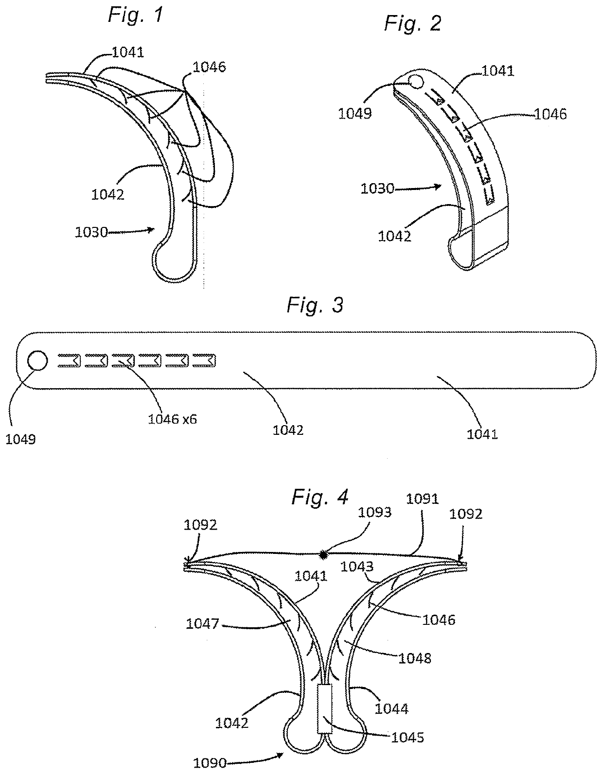
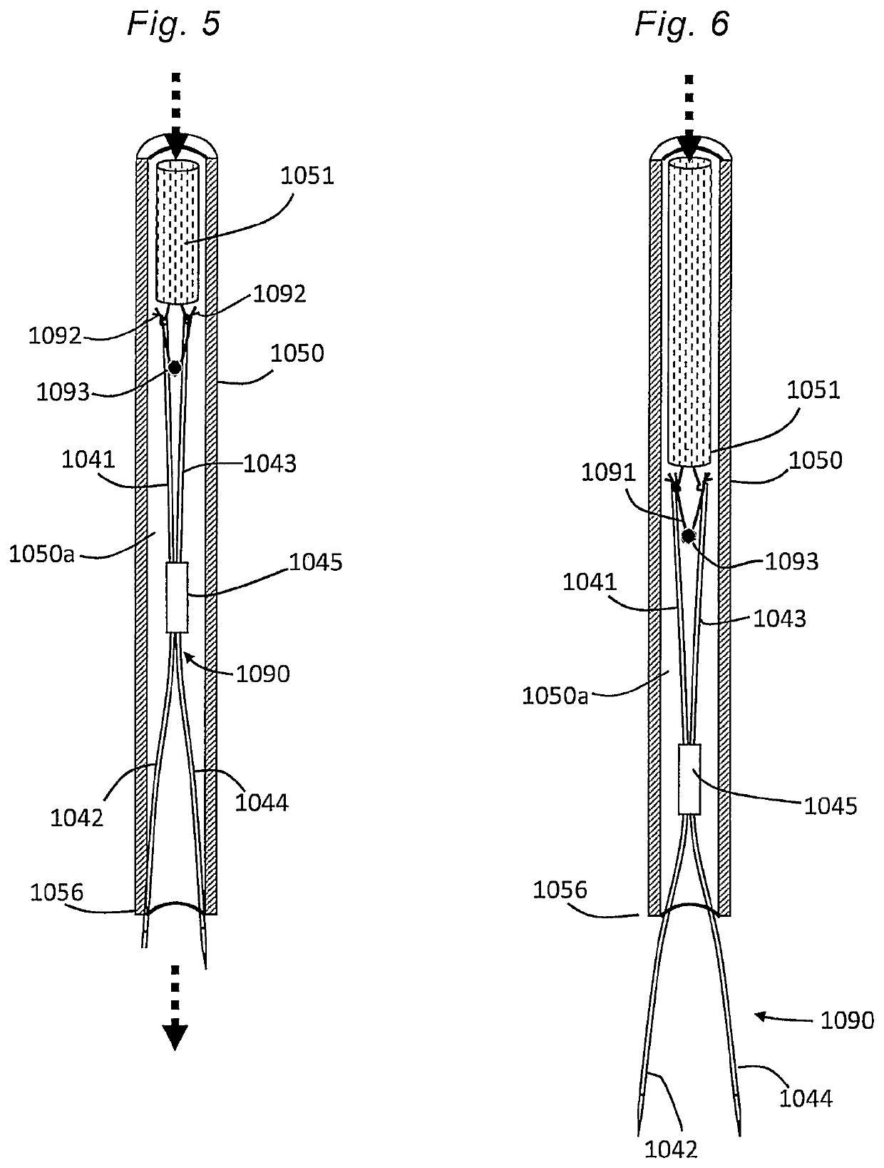
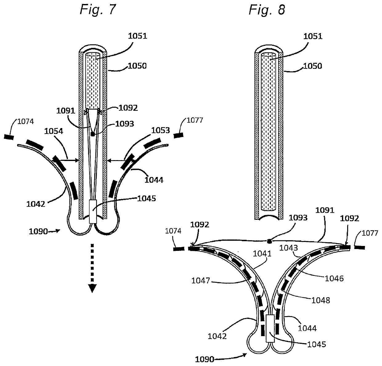
7]Described herein are embodiments of prosthetic devices that are primarily intended to be implanted at one of the mitral, aortic, tricuspid, or pulmonary valve regions of a human heart, as well as apparatuses and methods for implanting the same. The prosthetic devices can be used to help restore and / or replace the functionality of a defective native mitral valve. The disclosed embodiments should not be construed as limiting in any way. Instead, the present disclosure is directed toward all novel and nonobvious features and aspects of the various disclosed embodiments, alone and in various combinations and sub-combinations with one another. Further, although the primary intention is for use in humans, the disclosed embodiments may be configured to be used in animals too.

[0068]Grasping will preferably be atraumatic, which provides a number of benefits. By atraumatic, it is meant that the devices and methods of the invention may be applied to the valve leaflets and then removed withou...


PUM


Abstract

A clip for immobilizing leaflets of a cardiac or venous valve includes a hub having a pair of tangle resistant spring-biased outer arms coupled to an inferior end of the hub. A pair of tangle-resistant spring-biased inner arms lies adjacent to the outer arms and is coupled to a superior end of the hub. The clip may incorporate adjustable spacers and retrievable post implantation. A delivery catheter is used to position the valve clip adjacent a target valve while the outer and inner arms are biased in an opened position relative to each other. After the valve leaflets are located between the opened outer and inner arms, the biasing forces may be released to allow the clip to self-close over the valve leaflets.

Description

CROSS-REFERENCE TO RELATED APPLICATION[0001]This application is a continuation of PCT Application No. PCT / US2019 / 028788, filed Apr. 23, 2019, which claims the benefit of U.S. provisional patent application No. 62 / 662,152, filed on Apr. 24, 2018, the full disclosure of which is incorporated herein by reference.BACKGROUND OF THE INVENTION[0002]This disclosure pertains generally to medical devices and related methods for helping to seal native heart valves and / or augment and / or replace their function using retrievable tissue grasping devices, spacers, annulus reshaping devices, artificial valves, to prevent or reduce regurgitation there through, as well as delivery devices and related methods for implanting such prosthetic devices. More particularly, the present invention relates to methods and devices for the repair of mitral and tricuspid heart valves, venous valves, and other tissue structure through minimally invasive and other procedures.[0003]The native heart valves (i.e., the ao...

Claims


Application Information

Patent Timeline
Patent Type & Authority Applications(United States)
IPC IPC(8): A61F2/24
CPCA61F2/246A61F2/2463A61F2250/0003A61F2220/0008A61F2210/0014A61F2/2466
Inventor BASUDE, RAGHUVEERBASUDE, SHRI KRISHNA
Owner BASUDE RAGHUVEER
Why Eureka
Try Eureka