
Methods for Isothermal Molecular Amplification with Nanoparticle-Based Reactions

a technology nanoparticles, which is applied in the field of isothermal molecular amplification with nanoparticle-based reactions, can solve the problems of complex and costly methods for detection of infinite amounts of materials, and the challenge of using such optical methods in practical real-life applications, and achieves the effect of improving the sensitivity of other methods

Pending Publication Date: 2021-01-28
BROOKHAVEN SCI ASSOCS
View PDF1 Cites 0 Cited by
  • Summary
  • Abstract
  • Description
  • Claims
  • Application Information

AI Technical Summary

Benefits of technology

The method significantly increases the number of analyte molecules, enhancing the sensitivity of detection methods and allowing for sensitive detection of minute amounts of target molecules, thereby improving the practicality of bio-sensing and chemical safety applications.

Problems solved by technology

That is, such detection requires complex and costly methods to reveal infinitesimal amounts of materials.
However challenges may remain for use of such optical methods for practical real-life applications.

Method used


Image

  • Methods for Isothermal Molecular Amplification with Nanoparticle-Based Reactions
  • Methods for Isothermal Molecular Amplification with Nanoparticle-Based Reactions
  • Methods for Isothermal Molecular Amplification with Nanoparticle-Based Reactions

Examples


example 1

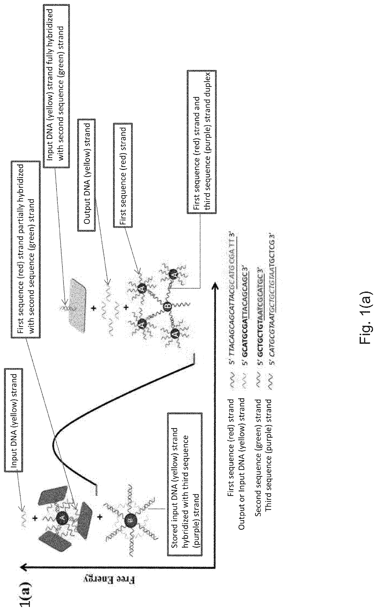
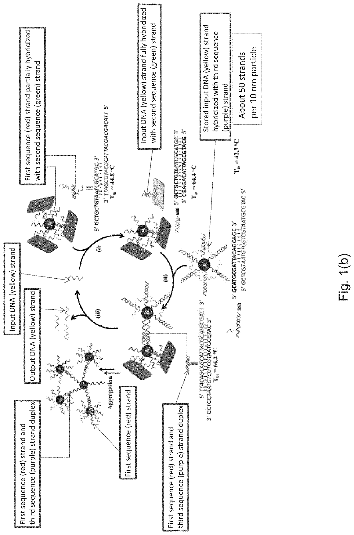
[0055]Begin with two 20 nm gold nanoparticles (AuNP), namely AuNP A (initial or deprotected particles A) and AuNP B (storage particles B), where each may be functionalized with ‘(red strand)’ first sequence strands and ‘(purple strand)’ third sequence strands of DNA, respectively. Red (first sequence) strands may be grafted on AuNP A and purple (third sequence) strands may be grafted on AuNP B. There may be an approximately 200 first sequence (red) strands on AuNP A and approximately 200 third sequence (purple) strands on AuNP B. AuNP A, in addition to the first sequence (red) strand, may be functionalized with a second sequence (green) strand. Part of the second sequence (green strand) of DNA may contain a sequence portion (5′ AAT CGC ATG C 3′—underlined) which may be complementary to the part of first sequence (red) strand of DNA sequence (5′GCA TGC GAT T 3′—underlined). First sequence and second sequence (green and red) strands of AuNP A may be partially hybridized. Due to select...

example 2

on and Characterization of AuNP-Origami Constructs (Protected Particles A)

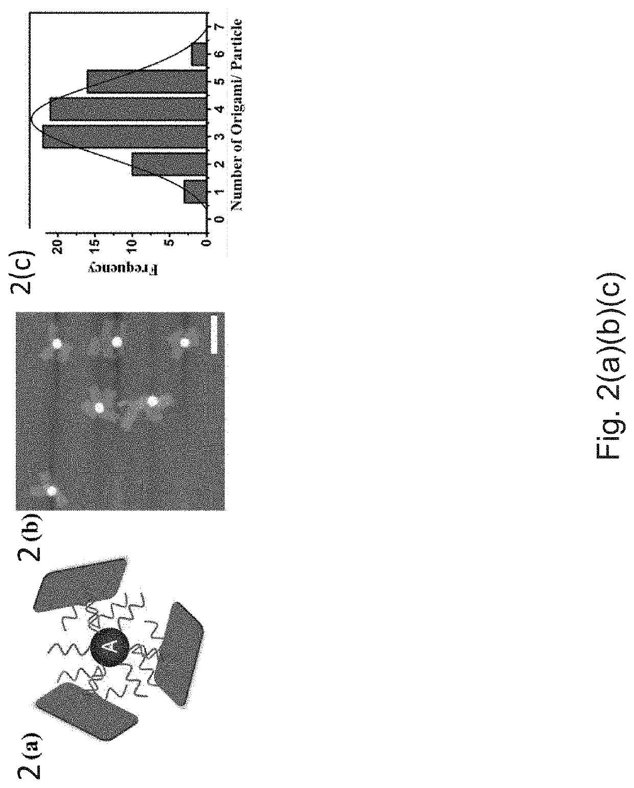
[0063]AuNP-Origami constructs were fabricated by mixing 20 nm AuNPs A and rectangular origami together (several per particle) by mixing and letting origami hybridize on initial or deprotected particles A.

[0064]After purification by known methods such as for example gel electrophoresis, atomic force microscopy (AFM) measurements were carried out to characterize origami-AuNP conjugates (protected particles A). An AFM image is shown in FIG. 2(b). The height profile extracted from AFM imaging shows several DNA origami structures with approximately 1.5 nm height that are connected to an approximately 18 nm height spherical AuNP (particles A) in high yield. There are very few unbound DNA origami found in the area of view suggesting serial purification was successful. In FIG. 2(c) a histogram of number of origami bound to one particle A is shown and the distribution fits a Gaussian profile. On an average 3-4 origami ...


PUM

PropertyMeasurementUnit
diameteraaaaaaaaaa
diameteraaaaaaaaaa
diameteraaaaaaaaaa

Abstract

The present method of detection involves increasing an amount of analyte molecules by an isothermal molecular amplification approach. In the present approach a starting molecule of interest may be amplified through a reaction it induces with specifically engineered and functionalized particles, namely protected particles A and storage particles B. This reaction may result in a set of output DNA molecules that is larger in number than the input DNA molecules. Thus the reaction between nanoparticles for amplification of a certain DNA sequence (input DNA molecules) may occur when there is a match with a targeted molecule (stored molecules on storage particles B) and if the DNA sequence of the input DNA molecules does not match (partially or completely) the targeted molecule the reaction may not occur. Without a certain molecular input of the input DNA molecule the reaction may not occur.

Description

CROSS-RELATED APPLICATION[0001]The present application is a divisional application of U.S. application Ser. No. 15 / 983,804, filed on May 18, 2018, which claims priority from U.S. Provisional Application No. 62 / 508,682, filed May 19, 2017, each of which is incorporated herein by reference in their entirety.STATEMENT OF GOVERNMENT RIGHTS[0002]The present application was made with government support under contract number DE-SC0012704 awarded by the U.S. Department of Energy. The United States government has certain rights in the invention(s).FIELD OF THE INVENTION[0003]This application relates to isothermal molecular amplification with nanoparticle-based reactions.BACKGROUND OF THE INVENTION[0004]Bio-sensing, counterfeit detection and chemical safety require sensitive detection of minute amounts of target molecules. That is, such detection requires complex and costly methods to reveal infinitesimal amounts of materials. In some cases, single molecule level detection may be achieved thr...

Claims


Application Information

Patent Timeline
Patent Type & Authority Applications(United States)
IPC IPC(8): C12Q1/6862B82Y5/00C12Q1/6853C12Q1/6844
CPCC12Q1/6862B82Y5/00C12Q2545/101C12Q1/6844C12Q1/6853C12Q2527/107C12Q2537/125C12Q2537/155C12Q2563/149C12Q2563/155
Inventor GANG, OLEGPAL, SUCHETAN
Owner BROOKHAVEN SCI ASSOCS
Learn More