
Substrate treating apparatus and substrate treating system having the same

a substrate treatment and substrate technology, applied in the direction of electrical equipment, basic electric elements, electric discharge tubes, etc., can solve the problems of multiple process defects in the icp process, serious damage to the protection layer along the profile of the upper electrode, and various process defects in the plasma process. to achieve the effect of minimizing plasma damage to the dielectric window

Pending Publication Date: 2021-01-28
SAMSUNG ELECTRONICS CO LTD
View PDF10 Cites 0 Cited by
  • Summary
  • Abstract
  • Description
  • Claims
  • Application Information

AI Technical Summary

Benefits of technology

The patent is about a plasma treating apparatus that has a special window made of dielectric material. This window has certain areas where a high level of etching is needed, and the apparatus has a layer to protect this window from damage caused by the plasma. This makes it possible to perform the etching process without causing harmful damage to the window.

Problems solved by technology

However, higher plasma density may cause more process defects in the ICP process, because the dielectric window tends to be etched away as the plasma density increases.
Although the lower surface of the body is covered with the protection layer, the continuous collision of the plasma occurs more intensively at a bias area of the protection layer along the profile of the upper electrode and may cause serious damage to the protection layer along the profile of the upper electrode.
Thus, the lower surface of the body of the dielectric window may be gradually etched away by the plasma, and then, the etched particles of the body may cause various process defects in the plasma process.

Method used


Image

  • Substrate treating apparatus and substrate treating system having the same
  • Substrate treating apparatus and substrate treating system having the same
  • Substrate treating apparatus and substrate treating system having the same

Examples


Embodiment Construction

[0023]Reference will now be made to example embodiments, which are illustrated in the accompanying drawings, wherein like reference numerals may refer to like components throughout.

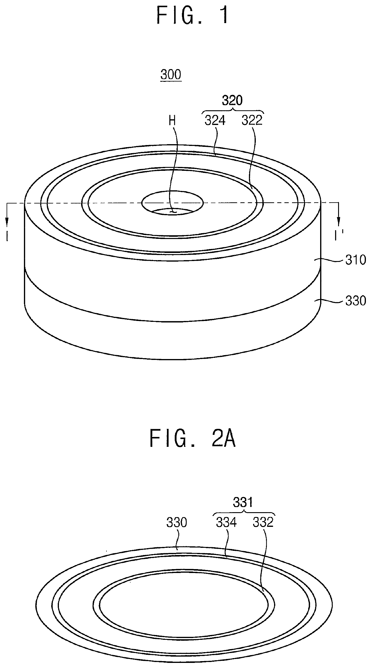
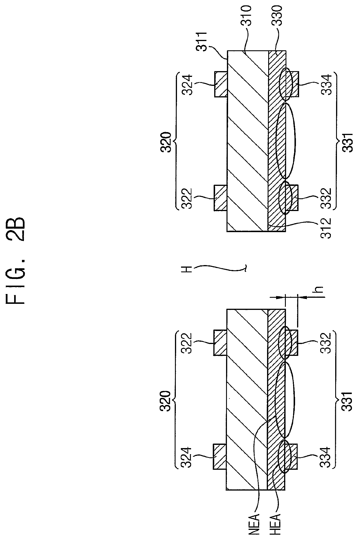
[0024]FIG. 1 is a perspective view illustrating a dielectric window for a substrate treating apparatus in accordance with an example embodiment. FIG. 2A is a rear view of the dielectric window shown in FIG. 1 and FIG. 2B is a cross-sectional view of the dielectric window cut along a line I-I′ of FIG. 1.

[0025]Referring to FIGS. 1, 2A and 2B, a dielectric window 300 in accordance with an example embodiment may include an insulative body 310, an antenna 320 on an upper surface 311 of the body 310, and to which a high frequency power may be applied to generate a plasma in a process space, and a protection layer 330 on a lower surface 312 of the body 310 in such a configuration that the protection layer 330 may be partially protruded towards the process space to thereby provide at least an etch resistor 331 on...


PUM

PropertyMeasurementUnit
thicknessaaaaaaaaaa
heightaaaaaaaaaa
thicknessaaaaaaaaaa

Abstract

A substrate treating apparatus, including a process chamber having a bottom portion configured to secure a substrate while a substrate treating process is performed on the substrate; and a dielectric window arranged at an upper portion of the process chamber to define a process space, and including: an insulative body, an antenna disposed on an upper surface of the insulative body, a protection layer disposed on a lower surface of the insulative body, and an etch resistor protruding from at least a portion of the protection layer toward the process space, wherein, based on power being applied to the antenna, a plasma is generated in the process space, and wherein the insulative body is protected from the plasma by the protection layer and the etch resistor.

Description

CROSS-REFERENCE TO RELATED APPLICATION[0001]This application claims priority under 35 U.S.C § 119 to Korean Patent Application No. 10-2019-0089415 filed on Jul. 24, 2019 in the Korean Intellectual Property Office, the contents of which are incorporated by reference herein in its entirety.BACKGROUND1. Field[0002]The disclosure relates to a substrate treating apparatus and a substrate treating system having the same, and more particularly, to a substrate treating apparatus having a dielectric window for generating a plasma in a process chamber and a substrate treating system having the same.2. Description of the Related Art[0003]Various substrate treating processes have been conducted for manufacturing semiconductor devices and semiconductor-applied apparatuses. For example, substrate treating processes have been conducted in a process space that is isolated from surroundings by a dielectric window, and in which an induced energy is generated.[0004]For example, an induced coupled plas...

Claims


Application Information

Patent Timeline
Patent Type & Authority Applications(United States)
IPC IPC(8): H01J37/32H01L21/67
CPCH01J37/32495H01L21/67069H01J37/32715H01J2237/334H01J37/3211H01J37/3244H01J37/32743H01J37/32119H01L21/67167H01J37/32467H01J37/32174H01J37/32532H01L21/6831H01L21/3065
Inventor KIM, SUNGYEONHONG, JUNGPYOKIM, KWANGNAMKIM, HYUNGJUNSUN, JONGWOO
Owner SAMSUNG ELECTRONICS CO LTD
Learn More