

Pattern forming method and semiconductor device manufacturing method
a semiconductor device and forming method technology, applied in semiconductor devices, basic electric elements, electrical equipment, etc., can solve problems such as difficulty in controlling the shape of patterns, increase junction leakage, and process stability, and achieve low energy consumption, high density, and refine pattern formation
- Summary
- Abstract
- Description
- Claims
- Application Information
AI Technical Summary
Benefits of technology
Problems solved by technology
Method used
Image

Examples
Embodiment Construction
[0038]An embodiment of the present invention will now be described in detail with reference to the accompanying drawings.
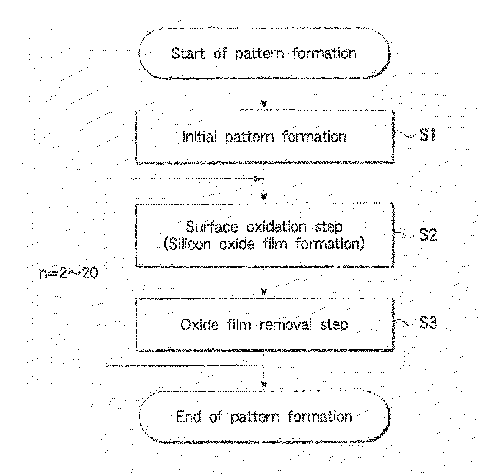
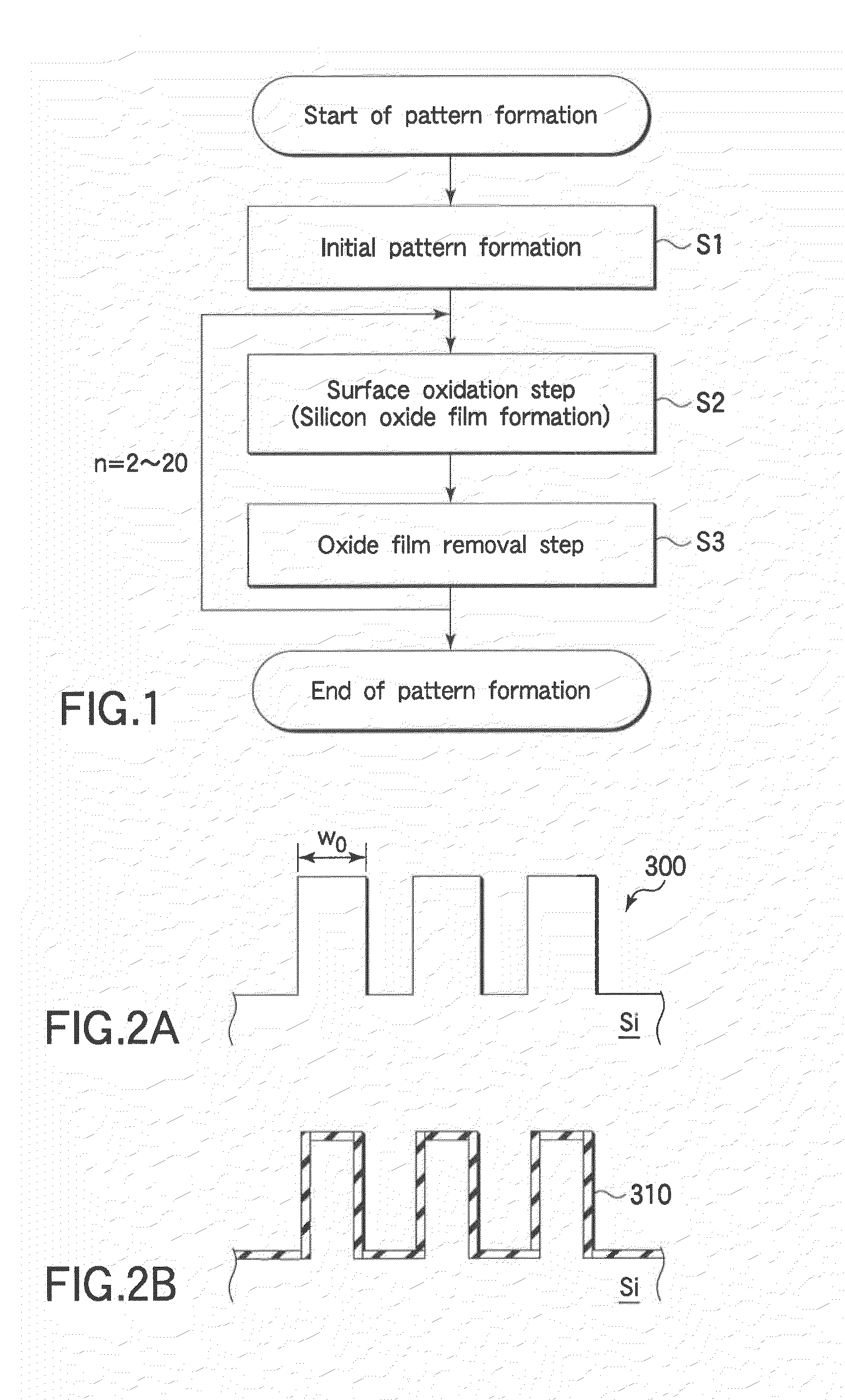
[0039]FIG. 1 is a flow chart showing a pattern forming method according to an embodiment of the present invention.
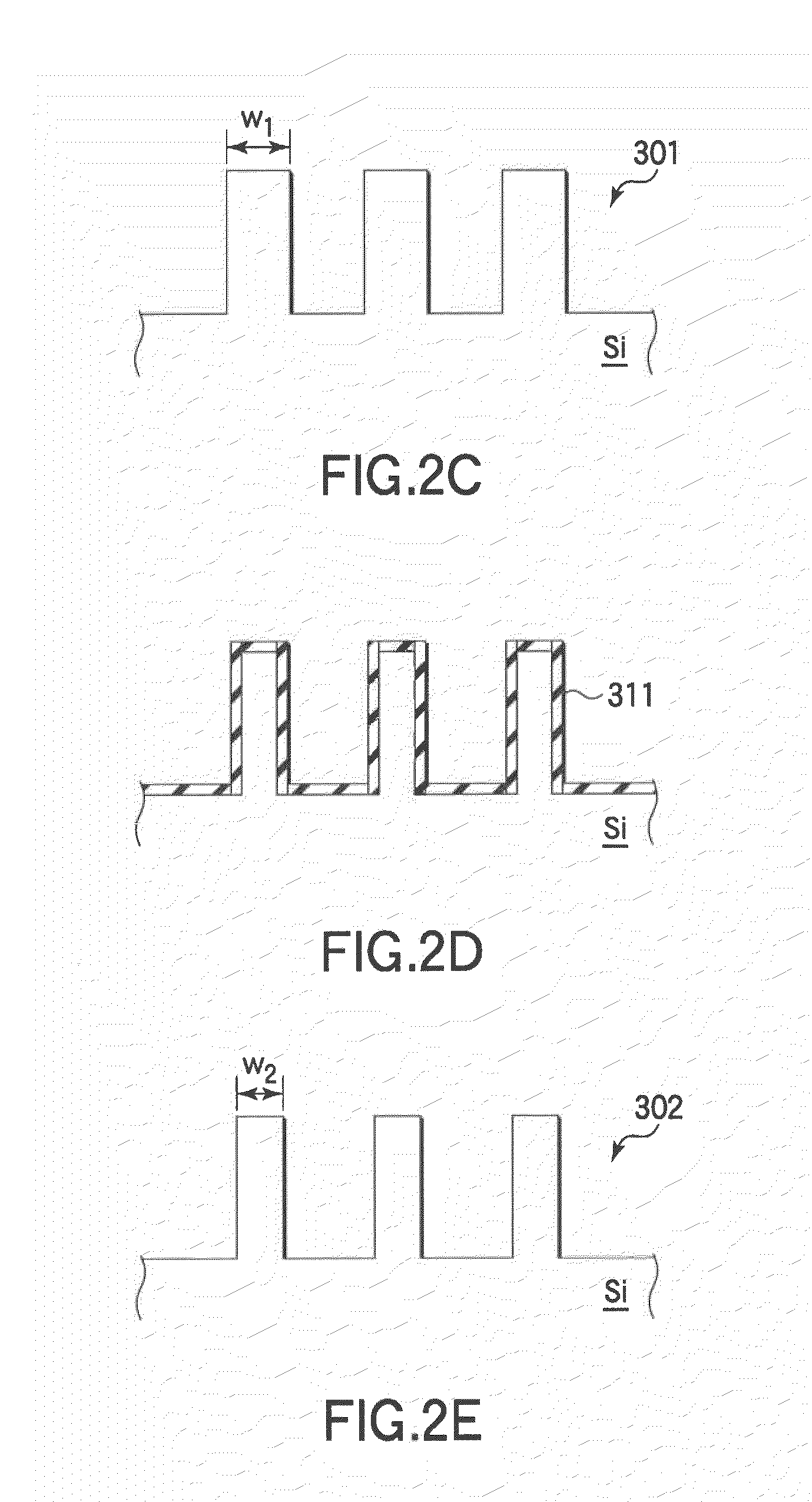
[0040]In a pattern forming method according to this embodiment, an initial pattern having a first line width is formed on a silicon surface of a target substrate (Step 1). This initial pattern may be formed by dry etching or the like through a resist mask with a pattern formed by, e.g., a photolithography technique. The surface thus etched has a surface roughness of 0.2 to 1 nm, which is acceptable, but a surface portion may be removed because part of the surface portion possibly suffers etching damage or the like.
[0041]Then, a plasma oxidation process is performed on the target substrate with the initial pattern formed thereon to oxidize the silicon surface to form a silicon oxide film (Step 2: surface oxidation step). This plasma oxidation process ma...
PUM
| Property | Measurement | Unit |
|---|---|---|
| width | aaaaa | aaaaa |
| thickness | aaaaa | aaaaa |
| pressure | aaaaa | aaaaa |
Abstract
Description
Claims
Application Information