Robotic arm having an extendable prismatic link

a prismatic link and robotic arm technology, applied in the field of robotic systems, can solve the problems of large fixed-length links, long fixed-length links, and inability to access patients, and achieve the effects of reducing the working angle, reducing the risk of collisions, and small form factor

Active Publication Date: 2021-02-04
VERB SURGICAL INC
View PDF0 Cites 6 Cited by
  • Summary
  • Abstract
  • Description
  • Claims
  • Application Information

AI Technical Summary

Benefits of technology

[0008]The working angle can depend on a home configuration of the robotic arm. More particularly, the robotic arm can have several home configurations in which the roll axis is orthogonal to the insertion axis, e.g., when the reference triangle is a right triangle. Several home configurations exist because the prismatic joint can extend and the pitch joints can rotate to form different right triangles. For each home configuration, the working angle can differ based on a distance between the first pitch joint and the remote center of motion for that home configuration. For example, as the remote center of motion is moved farther from the first pitch joint connecting the roll joint to the prismatic link, the working angle may decrease. Adjustment of the working angle can be chosen by selecting an appropriate home configuration to balance a range of motion of the surgical tool within the patient against the desire to redu...

Problems solved by technology

Several issues follow from the requirement for long, fixed-length links.
First, hardware-constrained robotic arms sweep out large spatial volumes during surgery, which can inhibit access to the patient by the surgeon or support staff who must avoid being hit by the arms.
Second, the long, fixed-length links are large, both visually and by volume and weight.
Thus, inertial loads of the links can be large, which must be acc...

Method used


Image

  • Robotic arm having an extendable prismatic link
  • Robotic arm having an extendable prismatic link
  • Robotic arm having an extendable prismatic link

Examples


Embodiment Construction

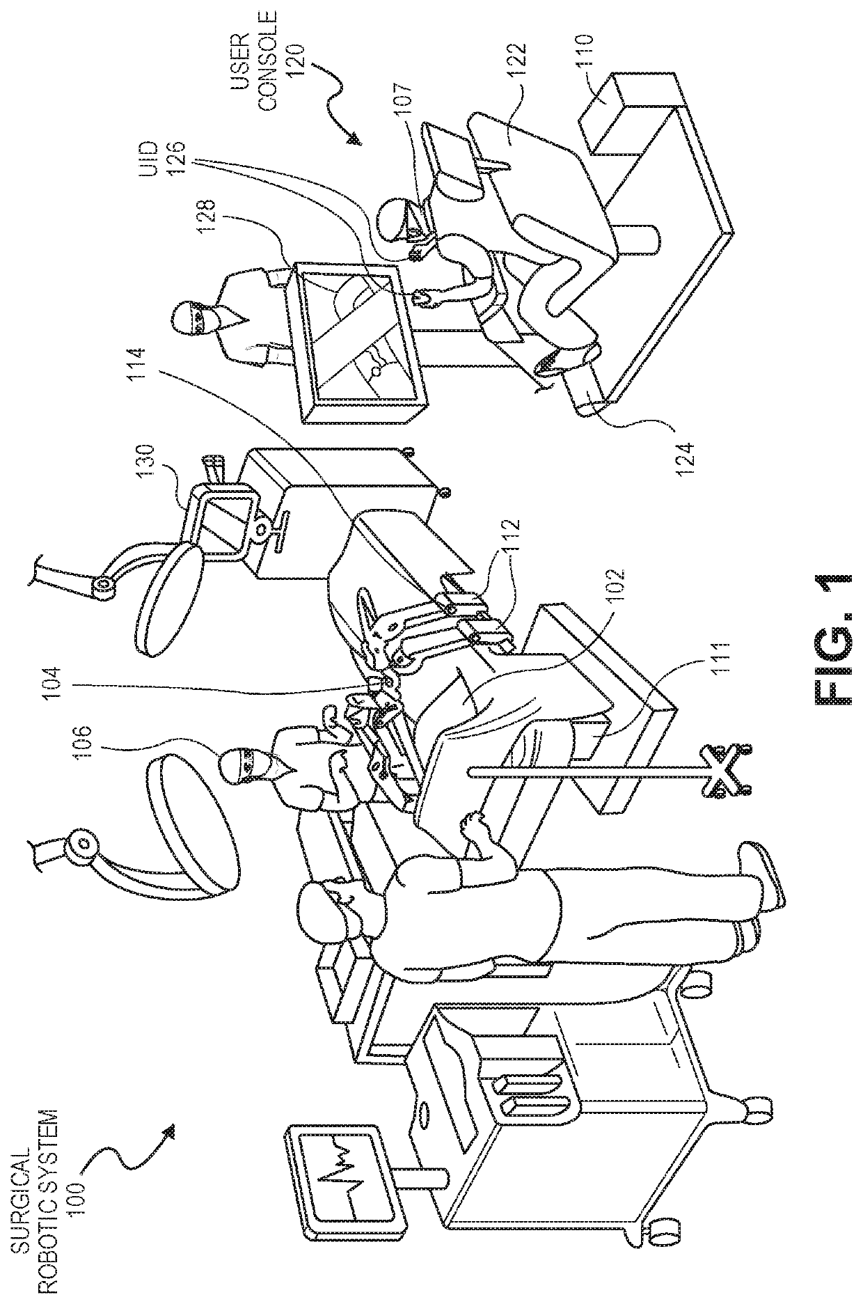
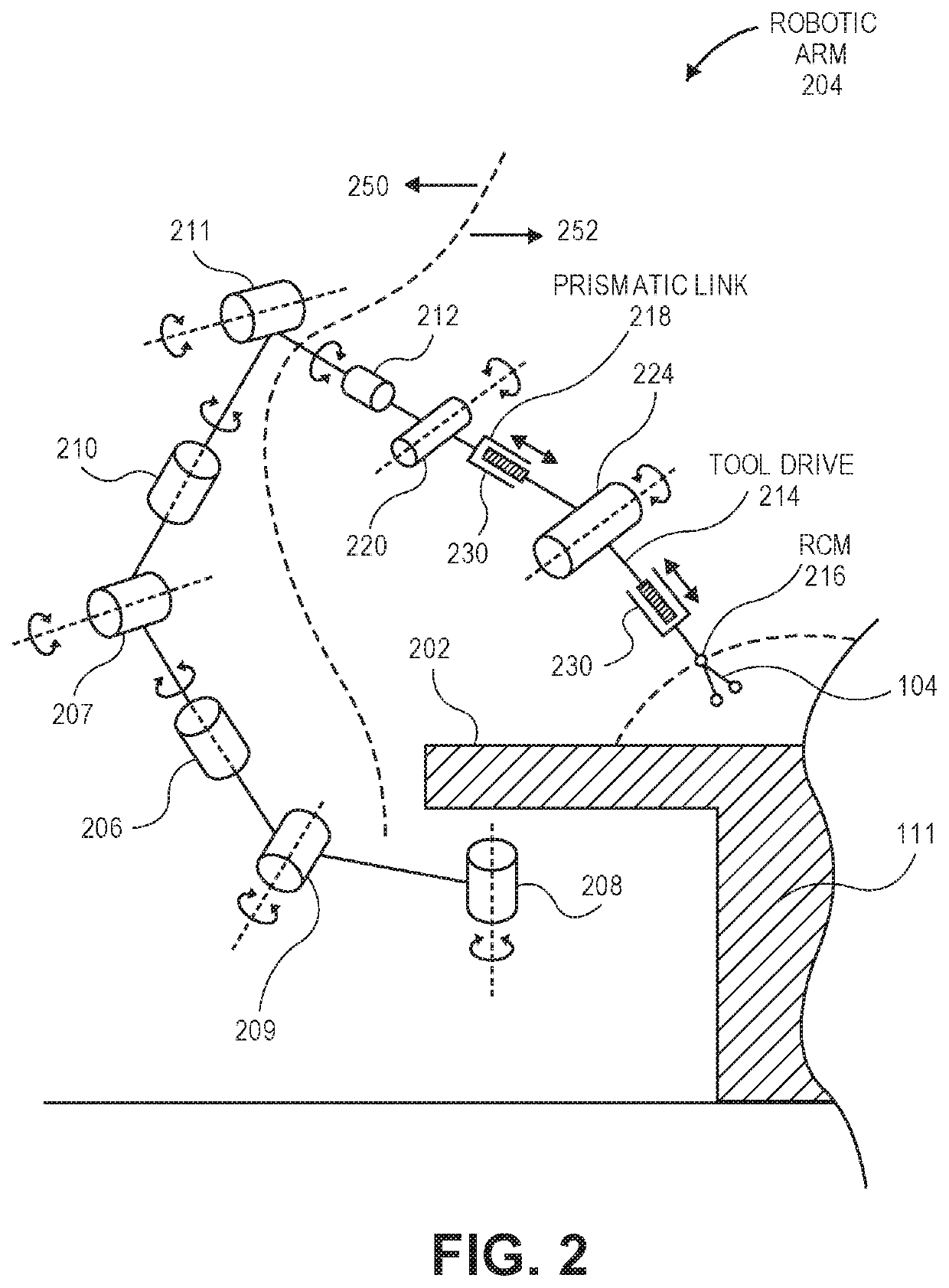
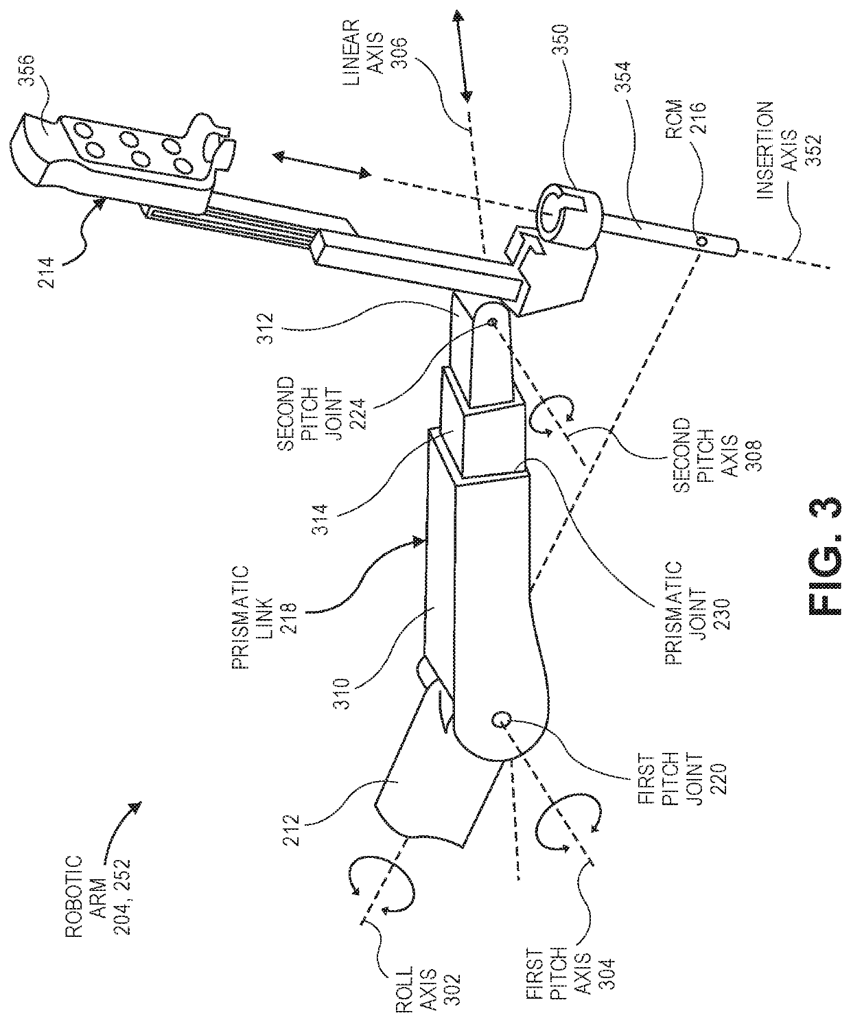
[0022]Embodiments describe a mechanical linkage and robotic systems incorporating such linkages. The mechanical linkage can be a robotic arm and the robotic system can be a surgical robotic system that incorporates the robotic arm to position a surgical tool during a robotic surgery. The mechanical linkage may, however, be used in other robotic systems, such as for manufacturing or military applications, to name only a few possible applications.

[0023]In various embodiments, description is made with reference to the figures. However, certain embodiments may be practiced without one or more of these specific details, or in combination with other known methods and configurations. In the following description, numerous specific details are set forth, such as specific configurations, dimensions, and processes, in order to provide a thorough understanding of the embodiments. In other instances, well-known processes and manufacturing techniques have not been described in particular detail ...


PUM


Abstract

Robotic arms and surgical robotic systems incorporating such arms are described. A robotic arm includes a roll joint connected to a prismatic link by a pitch joint and a tool drive connected to the prismatic link by another pitch joint. The prismatic link includes several prismatic sublinks that are connected by a prismatic joint. A surgical tool supported by the tool drive can insert into a patient along an insertion axis through a remote center of motion of the robotic arm. Movement of the robotic arm can be controlled to telescopically move the prismatic sublinks relative to each other by the prismatic joint while maintaining the remote center of motion fixed. Other embodiments are also described and claimed.

Description

BACKGROUNDFIELD[0001]Embodiments related to robotic systems are disclosed. More particularly, embodiments related to surgical robotic systems and corresponding mechanical linkages are disclosed.BACKGROUND INFORMATION[0002]Endoscopic surgery involves looking into a patient's body and performing surgery inside the body using endoscopes and other surgical tools. For example, laparoscopic surgery can use a laparascope to access and view an abdominal cavity. Endoscopic surgery can be performed using manual tools and / or a surgical robotic system having robotically-assisted tools.[0003]A surgical robotic system may be remotely operated by a surgeon to control a robotically-assisted tool located at an operating table. The surgical tool can be inserted into an access point in a patient, such as an incision in an abdominal wall of the patient. The surgeon may use a computer console located in the operating room, or it may be located in a different city, to command a robot to manipulate the su...

Claims


Application Information

Patent Timeline
IPC IPC(8): A61B34/35A61B34/00B25J9/00
CPCA61B34/35A61B34/20B25J9/0027A61B34/25A61B2017/00199A61B2017/00477A61B2017/00973A61B2034/2055A61B2034/2051A61B2017/00216A61B34/30A61B2034/305B25J18/02B25J9/06A61B34/77B25J9/1689A61B2017/00991B25J9/0039
Inventor DEVENGENZO, ROMANGARCIA KILROY, PABLO
Owner VERB SURGICAL INC
Why Eureka
Try Eureka