Respiratory mask assembly with a dynamic cuff

a dynamic cuff and mask technology, applied in the field of face mask aids, can solve the problems of tissue injury, ischemia and necrosis, air leakage between the face mask and the face, and pressure of 40 cm of h20 or higher being exerted on the skin of the face of the patient, so as to prevent tissue injury and necrosis, and prevent rebreathing.

Inactive Publication Date: 2021-02-04
ANANTHANARAYANAN KALYANARAMAN +2
View PDF0 Cites 0 Cited by
  • Summary
  • Abstract
  • Description
  • Claims
  • Application Information

AI Technical Summary

Benefits of technology

[0019]Hence, it is an object of this invention is to provide a suitable face mask which can provide adequate seal throughout the respiratory cycle, but not to expose the facial skin to supra inspiratory pressures continuously.
[0020]It is another object of this invention make this device less inconvenient to the patient compared to the existing devices.
[0021]It is a further object of this device to prevent and tissue injury and necrosis due to prolonged, continuous compression of the facial skin and soft tissues compared to the earlier devices.
[0022]It is a further object of this invention to make this device compatible with all types of anaesthesia and ventilation systems which are used both in hospitalized patients and for patients under home care.
[0023]It is yet another object of this invention to make this device compatible with all monitoring equipment's, humidifiers, capnographs, anaesthesia gas sensors and temperature monitors.
[0024]In any face mask or similar ventilating device, certain amount of exhaled gases accumulates near the mouth of the patient which is driven into the patient's lungs during the next inspiration. This space is called “Dead Space” of the apparatus, Yet another object of this invention is to keep the ‘Apparatus Dead Space’ minimal so that rebreathing can be prevented.

Problems solved by technology

Here the main problem is that the cuff will have to be pressed over the face of the patient at a pressure more than the Airway pressure to create an effective seal which is necessary to drive the anaesthetic / ventilator gases into the patient's airway, failing which the air will leak between the face mask and the face, as air always takes the path of least resistance.
This results in pressure of 40 cm of H20 or higher being exerted on the skin of the face of the patient for prolonged periods of time.
Prolonged compression of the face is not only very inconvenient for the patient but also can result in tissue injury, ischemia and necrosis.
This is uncomfortable for the patient beyond a few minutes.

Method used


Image

  • Respiratory mask assembly with a dynamic cuff
  • Respiratory mask assembly with a dynamic cuff

Examples


Embodiment Construction

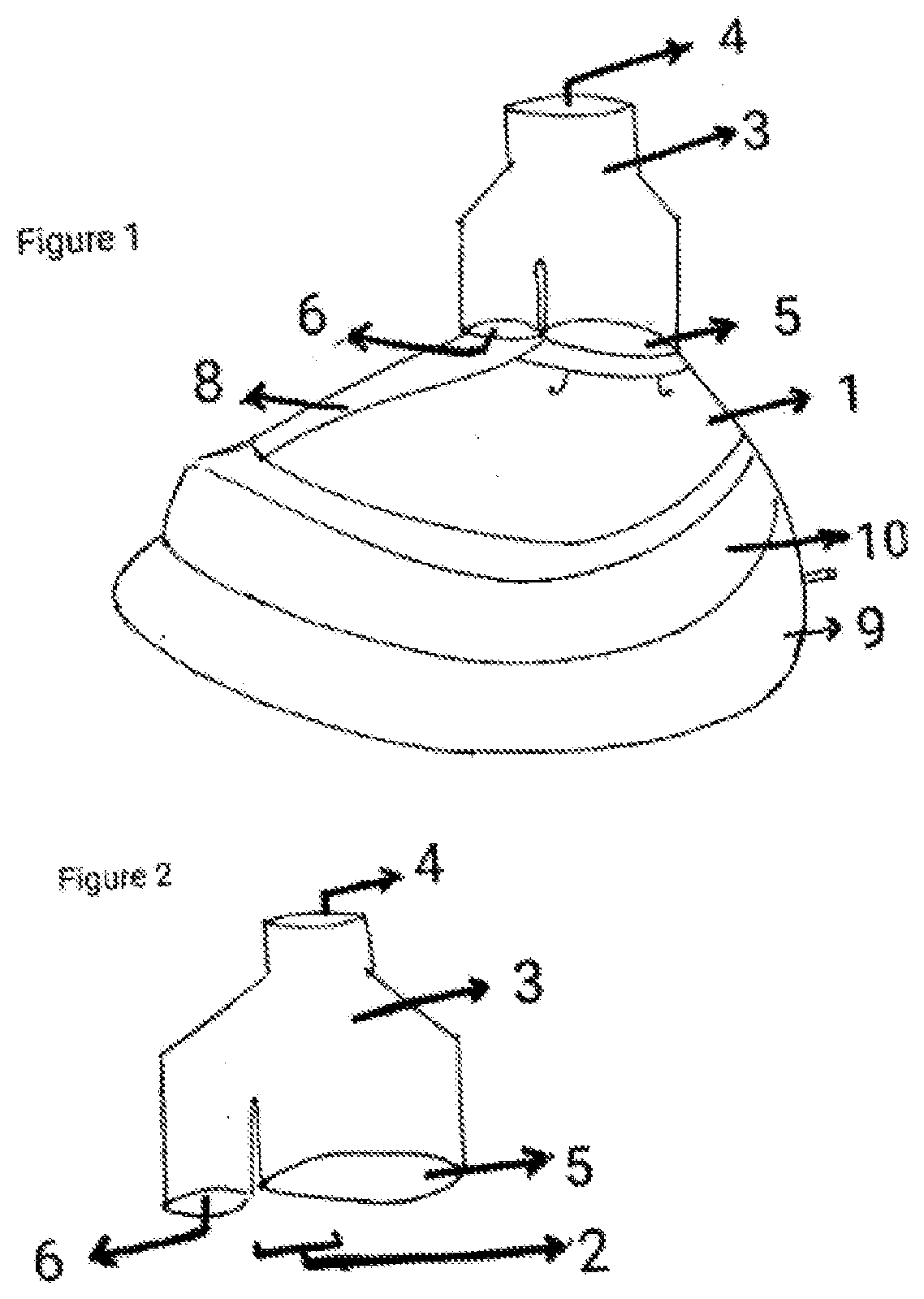
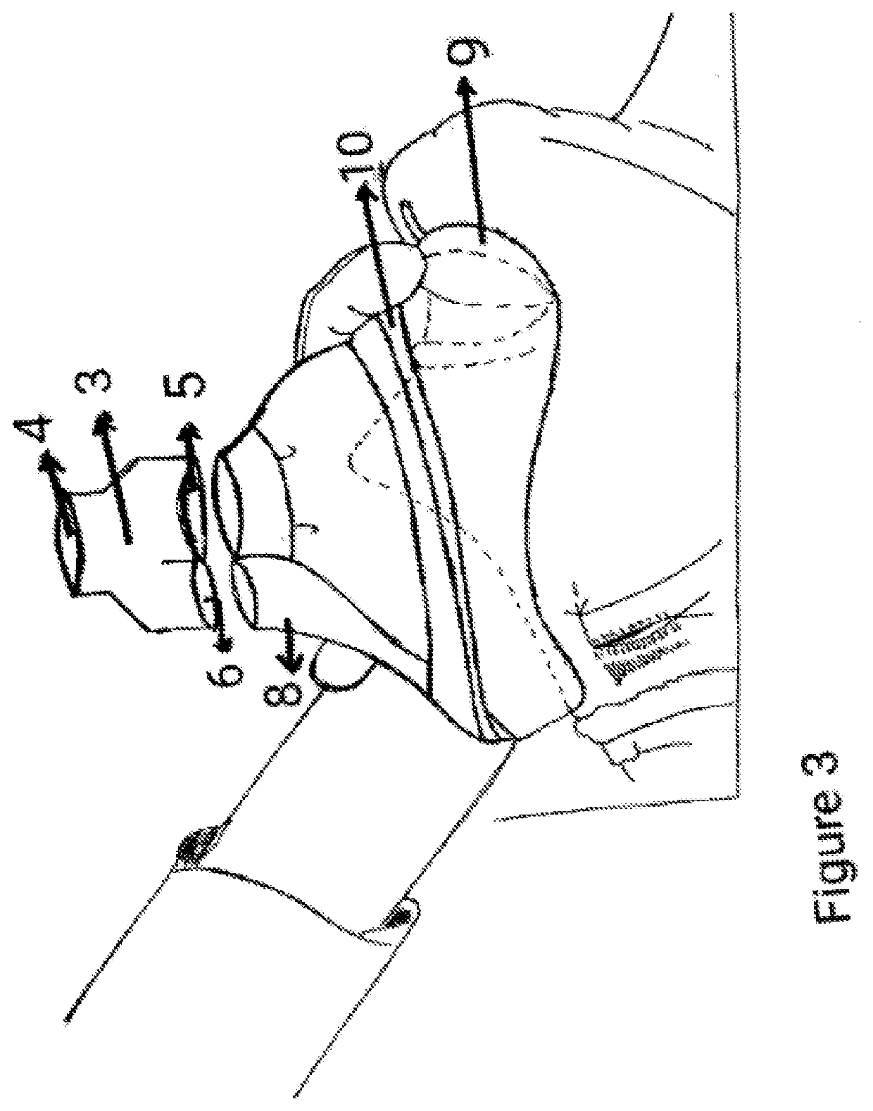
[0025]Fig No 1 shows the device as viewed front the side / lateral view. (1) denotes the body shell of the mask (2) denotes the Adaptor end where a specialised adaptor is connected. The specialised adaptor (3) has one proximal port (4) and two distal ports [shell port (5) and Dynacuff port (6)J. The proximal port is connected to the ventilator circuit through a standard connector. The shell port of the adaptor connects to the respiratory gas inlet of the shell body. The Dynacuff port of the specialised adaptor connects to the Dynacuff port of mask which leads to the dynamic cuff through a dedicated channel (8)

[0026]The Mask may be made of rigid plastic or any suitable transparent or opaque material. The specialised adaptor is made of rigid plastic or any other suitable material. The dynamic cuff (10) and the static cuff (9) are made either with polythene / silicone / latex rubber or any other suitable material.

[0027]Figure No 2 shows the specialised adaptor. Its proximal end contains the ...


PUM


Abstract

This invention is a device to be used with a system for supplying anaesthetic or respiratory gases into the airway of a human or an animal. This device is a face mask, which includes a main body or ‘shell’ which is lined with one or more air filled cuffs of which at least one cuff is closely reflecting the airway pressures generated inside the shell during the various phases of the respiratory cycle and is inflated by the gases supplied directly from the anaesthesia or ventilator circuit through a specialised adaptor and a dedicated inflation port. Many other advantages of the invention will be apparent from reading the description which follows in conjunction with the accompanying drawings

Description

THE FIELD OF THE INVENTION[0001]The present invention relates to a facemask aids during positive pressure ventilation and its specialised sealing system.[0002]This face mask “Mask” and its specialised adaptor, inflation system and the sealing cuffs are developed for providing ventilation and / or anaesthesia gases in the form of continuous or intermittent positive pressure ventilation (PPV), spontaneous respiration, jet ventilation or any such method of respiratory support, to a human or animal. Such a system can be used in patients under sedation / anaesthesia, or in patients on Non invasive ventilator (NIV) support in hospitalised patients or patients under home care, as required. The device can also be used in patients of Obstructive Sleep Apnea (OSA).[0003]The term ‘mask’ hereby intended to include all respiratory devices which provide which provide a seal enabling positive pressure ventilation of a human or animal when applied on the face covering either a portion of or whole of th...

Claims


Application Information

Patent Timeline
Patent Type & Authority Applications(United States)
IPC IPC(8): A61M16/06A61M16/04A61M16/01
CPCA61M16/0605A61M16/0688A61M16/01A61M16/045A61M16/0816A61M16/0452A61M16/06A61M16/0833
Inventor ANANTHANARAYANAN, KALYANARAMANNIRAV, KOTAKASHISH, PATYAL
Owner ANANTHANARAYANAN KALYANARAMAN
Why Eureka
Try Eureka