Unlock instant, AI-driven research and patent intelligence for your innovation.

Electronic device, control method, and non-transitory computer readable medium

a control method and electronic technology, applied in the field of electronic devices, can solve the problems of inability to improve the accuracy of viewed point estimation in the state of the head, invite increases in the complexity and cost of the device, and cannot achieve the effect of high precision and simple configuration

Active Publication Date: 2021-02-04
CANON KK
View PDF0 Cites 0 Cited by
  • Summary
  • Abstract
  • Description
  • Claims
  • Application Information

AI Technical Summary

Benefits of technology

The invention provides a technique for detecting when an eye is not looking at the center of a screen and can't accurately estimate the position of the eye. This can be done using a simple electronic device that captures images of the eye through a window frame. The invention can be used in electronic devices such as smartphones or computers to improve user experience and make interactions more efficient.

Problems solved by technology

However, when the user shifts his / her face relative to the viewfinder or the like such that the head performs a large translational motion, the pupil image and Purkinje image on the eye image also perform a large translational motion, and as a result, the viewed point cannot be estimated with a high degree of precision.
However, a configuration for capturing an image of the entire face (the entire head) is required, inviting increases in the complexity and cost of the device.
Furthermore, the viewed point estimation precision cannot be improved in states where the head is hidden and the image of the head cannot be captured, such as a state where the user is looking through the viewfinder of the camera or a state where the user is wearing VR glasses (VR goggles).
However, a ghost image generated by the eyeball lamp may appear on the eye image, making it impossible to estimate the viewed point with a high degree of precision.
When estimating the viewed point, therefore, the image display range cannot be switched to an appropriate range, and as a result, the viewed point cannot be estimated with a high degree of precision.

Method used


Image

  • Electronic device, control method, and non-transitory computer readable medium
  • Electronic device, control method, and non-transitory computer readable medium
  • Electronic device, control method, and non-transitory computer readable medium

Examples


first embodiment

[0052]A first embodiment of the present invention will be described below with reference to the attached figures.

[0053]Description of Configuration

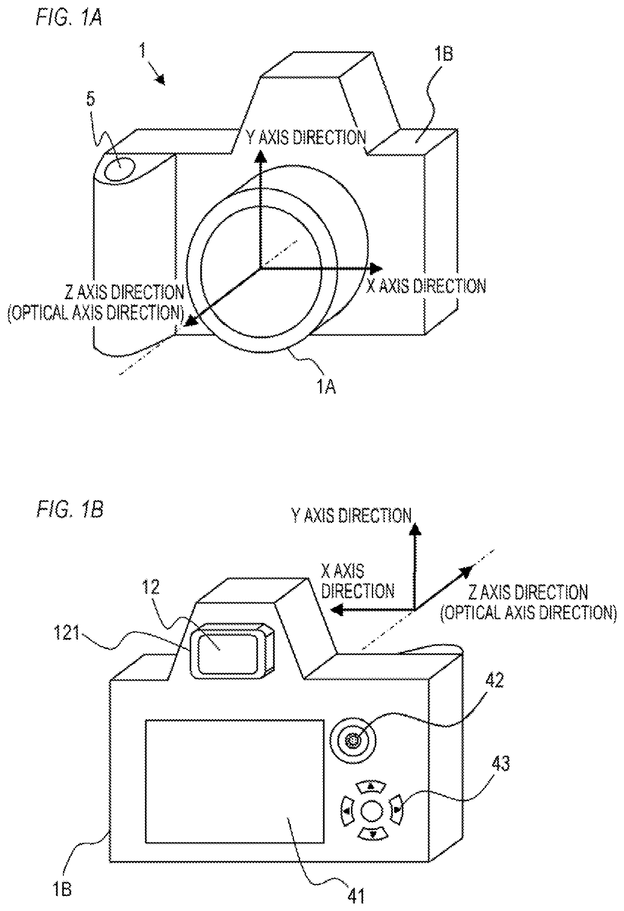
[0054]FIGS. 1A and 1B show the outer appearance of a camera 1 (a digital still camera; an interchangeable lens camera) according to a first embodiment. FIG. 1A is a front perspective view, and FIG. 1B is a back perspective view. As shown in FIG. 1A, the camera 1 includes an image-capturing lens unit 1A and a camera housing 1B. A release button 5, which is an operating member that receives image capturing operations from a user (a photographer), is disposed on the camera housing 1B. As shown in FIG. 1B, an eyepiece window frame 121 and an eyepiece lens 12 (an eyepiece optical system) through which the user looks at a display device 10 (a display panel), to be described below, provided inside the camera housing 1B are disposed on a back surface of the camera housing 1B. The eyepiece window frame 121 surrounds the eyepiece lens 12 and projec...

second embodiment

[0126]A second embodiment of the present invention will now be described. Note that below, description of the same points (configurations, processing, and so on) as in the first embodiment will be omitted, and points that differ from the first embodiment will be described. In the example described in the first embodiment, the oblique look-through state is detected while displaying the through image. In the second embodiment, an example in which the oblique look-through state is detected during the calibration operation will be described. Further, in the second embodiment, an example in which an image display range (the range in which an image is displayed) within the viewfinder is determined on the basis of the oblique look-through state detection result will be described. More specifically, an example in which the image display range of the display device 10 is determined on the basis of the oblique look-through state detection result so as to prompt the user to look through the vi...

third embodiment

[0169]A third embodiment of the present invention will now be described. Note that below, description of the same points (configurations, processing, and so on) as in the second embodiment will be omitted, and points that differ from the second embodiment will be described. In the example described in the second embodiment, the image display range is reduced. In the third embodiment, an example in which the image display range is moved will be described.

[0170]Description of Viewing State Improvement Method

[0171]As described above, the user adopts the oblique look-through state when the visual line of the user is blocked by the eyepiece window frame or the like so that the user cannot see the edges of the display device 10 (the screen). Hence, in the third embodiment, when the oblique look-through state is detected, the image display range of the display device 10 is moved from the current range and set.

[0172]FIG. 17A shows an image display state before detecting the oblique look-thr...


PUM


Abstract

An electronic device according to the present invention is an electronic device capable of acquiring an eye image by capturing an image of an eye looking at a screen of a display through an eye window frame, and includes at least one memory and at least one processor which function as: an estimating unit configured to estimate a viewed point of the eye on the screen on a basis of the eye image; and a detecting unit configured to detect a shifted viewing state in which the eye shifts from a position corresponding to a center of the screen on the eye image, on a basis of a position of a pupil image or a Purkinje image on the eye image.

Description

BACKGROUND OF THE INVENTIONField of the Invention[0001]The present invention relates to an electronic device capable of estimating (detecting) a viewed point.Description of the Related Art[0002]Recent years have witnessed advances in camera automation and intelligentization. Japanese Patent Application Publication No. 2004-8323 proposes a technique for recognizing the intended object of a photographer looking through a viewfinder and controlling the focus on the basis of information about the viewed point (the visual line position) of the photographer, without manually inputting an object position. Japanese Patent Application Publication No. 2009-104524 proposes a technique for improving the precision of viewed point detection by taking into consideration the angle of rotation and position of the head in addition to the angle of rotation of the eyeball. Japanese Translation of PCT Application Publication No. 2018-506781 proposes a technique in which a plurality of eyeball lamps are ...

Claims


Application Information

Patent Timeline
IPC IPC(8): G06F3/01G06T7/70H04N5/232H04N5/225
CPCG06F3/013G06T7/70G06T2207/30201H04N5/232945H04N5/2256H04N5/232935H04N23/63H04N23/56H04N23/632H04N23/635
Inventor UCHIDA, TAKESHI
Owner CANON KK