Method for setting rolling mill, and rolling mill

a technology of rolling mill and setting method, which is applied in the direction of measuring device, rolling speed control device, manufacturing tool, etc., can solve the problem of difficult to directly measure such a thrust force, and achieve the effect of suppressing the occurrence of reducing the thrust force generated between rolls, and reducing the zigzagging and camber of workpieces

Active Publication Date: 2021-02-11
NIPPON STEEL CORP
View PDF0 Cites 2 Cited by
  • Summary
  • Abstract
  • Description
  • Claims
  • Application Information

AI Technical Summary

Benefits of technology

[0024]As described above, according to the present invention, thrust forces generated between rolls can be reduced and the occurrence of zigzagging and camber of a workpiece can be suppressed.

Problems solved by technology

In a hot rolling process, for example, zigzagging of a steel plate occurs as a phenomenon that is the cause of rolling trouble.
A thrust force that is generated at a minute cross (also referred to as “roll skew”) between rolls of a rolling apparatus is one cause of zigzagging of a steel plate, and it is difficult to directly measure such a thrust force.

Method used


Image

  • Method for setting rolling mill, and rolling mill
  • Method for setting rolling mill, and rolling mill
  • Method for setting rolling mill, and rolling mill

Examples


first embodiment

2. First Embodiment

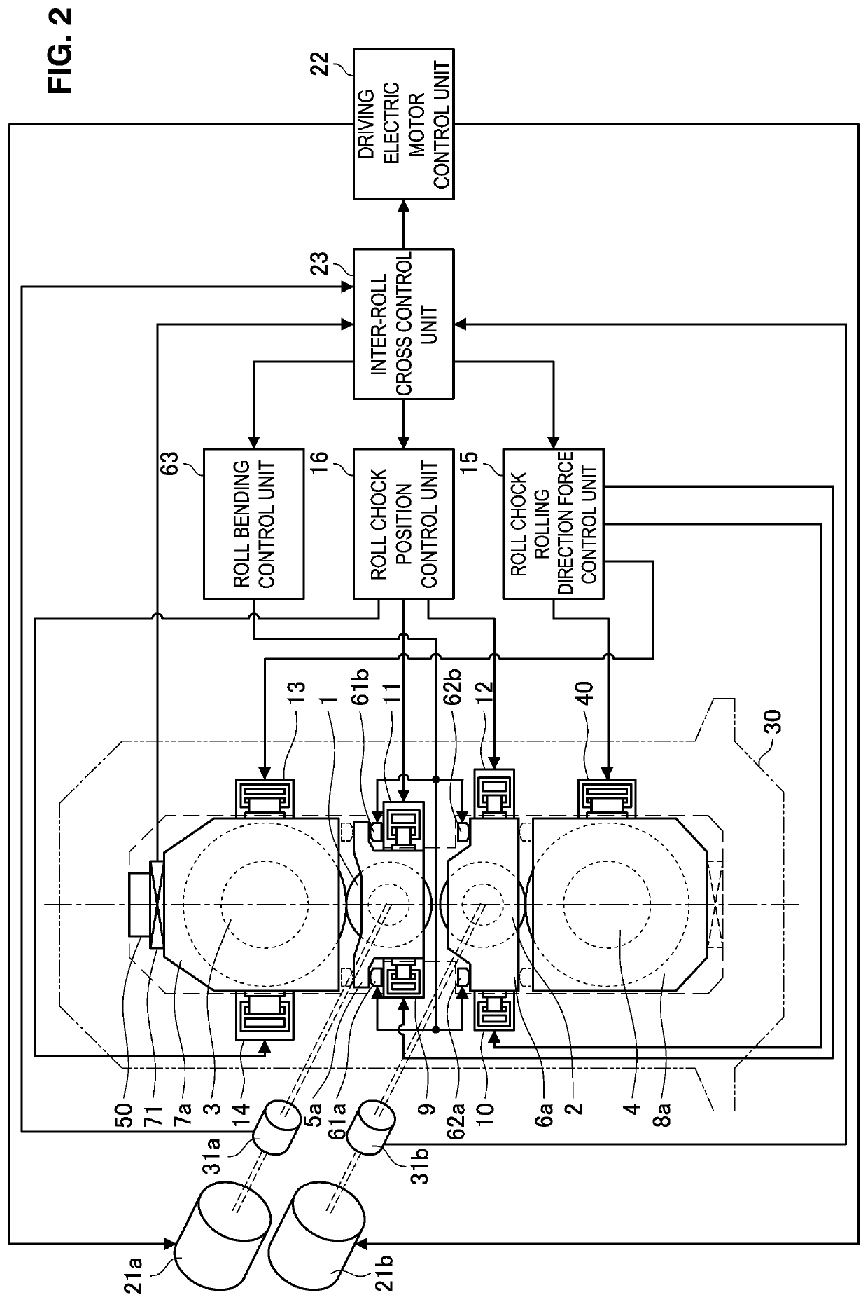
[0067]The configuration of a rolling mill and an apparatus for controlling the rolling mill, as well as a method for setting the rolling mill according to a first embodiment of the present invention will be described based on FIG. 2 to FIG. 4. In the first embodiment, before reduction position zero point adjustment or before the start of rolling, the positions of roll chocks are adjusted so as to make an inter-roll cross angle between a backup roll serving as a reference and other rolls zero, and thus rolling in which a thrust force does not arise is realized.

[0068][2-1. Configuration of Rolling Mill]

[0069]First, the rolling mill according to the present embodiment and an apparatus for controlling the rolling mill will be described based on FIG. 2. FIG. 2 is an explanatory drawing illustrating the configuration of the rolling mill according to the present embodiment and an apparatus for controlling the rolling mill. Note that, it is assumed that the rolling mill i...

second embodiment

3. Second Embodiment

[0108]Next, the configuration of a rolling mill and an apparatus for controlling the rolling mill, as well as a method for setting the rolling mill according to a second embodiment of the present invention will be described based on FIG. 5 to FIG. 7C. The rolling mill according to the second embodiment is a so-called “single drive mill” in which the upper work roll 1 and the lower work roll 2 are driven by one driving electric motor 21 through a pinion stand (not illustrated in the drawings) or the like. Therefore, in the case of adjusting roll chock positions based on the motor torque, only one roll assembly among the upper roll assembly and the lower roll assembly can be adjusted. Hereunder, the configuration of the rolling mill as well as a method for setting the rolling mill according to the present embodiment are described in detail.

[0109][3-1. Configuration of Rolling Mill]

[0110]First, the rolling mill according to the present embodiment and an apparatus fo...

example 1

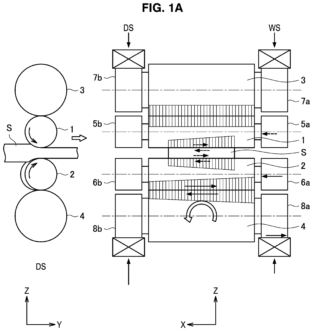
[0160]A conventional method and the method of the present invention were compared in relation to reduction leveling setting that takes into consideration the influence of a thrust force due to an inter-roll cross in a so-called “twin-drive hot rolled thick-gauge plate rolling mill” in which the upper work roll 1 and the lower work roll 2 are configured to be independently rotatable that is illustrated in FIG. 2.

[0161]First, in the conventional method, without using the functions of the inter-roll crossing control unit of the present invention, replacement of housing liners and chock liners was periodically performed, and equipment management was conducted so that an inter-roll cross would not occur.

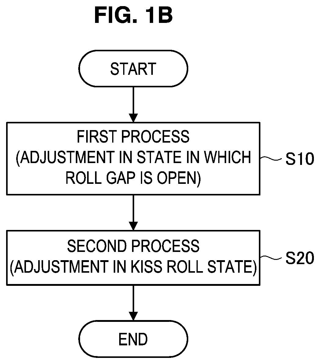
[0162]On the other hand, in the method of the present invention, using the functions of the inter-roll cross control unit according to the first embodiment that is described above, adjustment of the positions of roll chocks was performed in accordance with the processing flow illustrated ...


PUM

PropertyMeasurementUnit
diameteraaaaaaaaaa
widthaaaaaaaaaa
widthaaaaaaaaaa

Abstract

A method for setting a rolling mill, the method being executed before reduction position zero point adjustment or before the start of rolling, and including: a first process of setting rolls in an open state, and with respect to each of the upper roll assembly and the lower roll assembly, adjusting positions of roll chocks in a rolling direction based on a torque acting on the work roll or a vertical roll load difference; and a second process of, after the first process, setting rolls in a kiss roll state, measuring a vertical roll load in two rotational states on a work side and a drive side, and moving roll chocks of a roll assembly on the opposite side to a reference roll simultaneously and in a same direction so that the vertical roll load difference falls within an allowable range to thereby adjust the positions of the roll chocks.

Description

TECHNICAL FIELD[0001]The present invention relates to a rolling mill that rolls a workpiece, and a method for setting the rolling mill.BACKGROUND ART[0002]In a hot rolling process, for example, zigzagging of a steel plate occurs as a phenomenon that is the cause of rolling trouble. A thrust force that is generated at a minute cross (also referred to as “roll skew”) between rolls of a rolling apparatus is one cause of zigzagging of a steel plate, and it is difficult to directly measure such a thrust force. Therefore, in the past it has been proposed to measure a thrust counterforce that is detected as a counterforce that is the total value of thrust forces generated between rolls or a roll skew angle, and identify the thrust force generated between rolls based on the thrust counterforce or the roll skew angle and perform zigzagging control of the steel plate.[0003]For example, Patent Document 1 discloses a plate rolling method which measures a thrust counterforce in the axial directi...

Claims


Application Information

Patent Timeline
Patent Type & Authority Applications(United States)
IPC IPC(8): B21B31/02B21B38/08B21C51/00B21B37/46
CPCB21B31/02B21B37/46B21C51/00B21B38/08B21B38/105B21B2275/12B21B2265/12B21B31/185B21B37/007
Inventor ISHII, ATSUSHIYAMAGUCHI, KAZUMANIKKUNI, DAISUKE
Owner NIPPON STEEL CORP
Why Eureka
Try Eureka