
A system for transporting biomass material and a method for preventing blow back in said system

a biomass material and system technology, applied in the field of biomass material transportation system and a method for preventing blowback in the system, can solve the problem that minor amounts of gas will always be able to penetrate the plug, and achieve the effect of reducing the risk of blowback

Inactive Publication Date: 2021-02-11
VALMET AB
View PDF6 Cites 2 Cited by
  • Summary
  • Abstract
  • Description
  • Claims
  • Application Information

AI Technical Summary

Benefits of technology

This patent is about a system and method to prevent material from being forced back into a pressurized area, which can cause damage and potentially start a fire. The technical effect of this invention is to reduce the risk of blow-back when feeding biomass material to a pressurized zone.

Problems solved by technology

However, minor amounts of gas will always be able to penetrate the plug.

Method used


Image

  • A system for transporting biomass material and a method for preventing blow back in said system

Examples


first embodiment

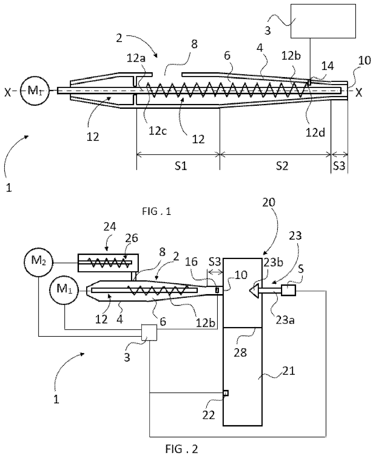
[0045]FIG. 1 illustrates a system 1 according to the invention comprising a feeding device 2 in the form of a plug screw feeder and a control unit 3.

[0046]The feeding device 2 comprises a housing 4 that defines a channel 6 that extends along a longitudinal axis X of the feeding device 2. The channel 6 is divided into an inlet section 51, an intermediate section S2 and an outlet section S3. The inlet section 51 comprises an inlet 8 for biomass material and the outlet section S3 comprises an outlet 10 for biomass material. The inlet 8 is adapted to be connected to a feeding device (not shown) for feeding 25 biomass into the channel 6. Such a feeding device may, for example, comprise a force feed screw adapted to transport the biomass towards the inlet 8. The outlet 10 is adapted to be connected to a charger (not shown) to allow the biomass to be discharged from the channel 6 and into said charger.

[0047]A feed screw 12 extends into the housing 4 along the longitudinal axis X of the fee...

second embodiment

[0053]FIG. 2 is a schematic view of a system 1 according to the invention. The system 1 comprises a feeding device 2 similar to the feeding device 2 in FIG. 1, the only difference being that the primary measuring unit 16 in FIG. 2 is a strain gauge (schematically shown) attached to an outside of the housing 4 of the feeding device 2. The electric resistance of the primary measuring unit 16 varies with the length of the primary measuring unit 16 and thus the length of the corresponding part of the housing 4, and the length of the corresponding part of the housing 4 varies with the radial pressure that the plug of biomass exerts on the inside of the channel 6, wherefore the electric resistance is a variable that is indicative of the radial force applied by the plug of biomass and thus also the gas permeability of the plug of biomass. The primary measuring unit 16 in FIG. 2 is arranged within the outlet section S3 close to the outlet 10.

[0054]The system 1 also comprises a feeding devic...


PUM

PropertyMeasurementUnit
Timeaaaaaaaaaa
Temperatureaaaaaaaaaa
Forceaaaaaaaaaa

Abstract

The invention relates to a system (1) comprising a feeding device (2) comprising a channel (6) having an inlet (8) and an outlet (10) and a feed screw (12) for conveying biomass material through the channel. The feed screw comprises a screw flight (12b) that extends from a first end (12c) to a second end (12d) and is adapted to form a gas impermeable plug of biomass. The system comprises at least one primary measuring unit (14; 16) adapted to continuously measure a primary variable indicative of the gas permeability of the plug, which primary measuring unit is connected to said feeding device between the first end of the screw flight and the outlet; and a control unit (3) adapted to use said primary variable values to monitor the gas permeability of the plug. The invention also relates to a method for preventing blow back in the above described system.

Description

TECHNICAL FIELD[0001]The invention relates to a system for transporting biomass material and a method for preventing blow back in said system.BACKGROUND[0002]It is known to use feeding devices comprising one or more force feeding screws for conveying biomass from one part of a pulping process to another part of said pulping process. These devices may also be used for dewatering of the biomass during transport. When biomass is transported to a pressurized zone, the force feeding screws are suitably adapted to compress said biomass during transport to form a gas impermeable plug of biomass within the feeding device to prevent gas from the pressurized zone from flowing back against the biomass transport direction through the force feeding screw, so-called blow-back. Such feeding devices are referred to as plug screw feeders.[0003]It is also known to arrange a blow back damper at a plug screw feeder outlet, which blow back damper is adapted to apply a counter pressure on the biomass dis...

Claims


Application Information

Patent Timeline
IPC IPC(8): B65G43/02D21C7/06B65G33/22B30B9/12
CPCB65G43/02D21C7/06B65G33/22B65G2203/045B65G2203/0208B65G2203/042B65G2201/04B30B9/125D21B1/00B30B11/24B30B9/3096B30B9/3007B30B9/12B65G33/00B65G53/00B01J2208/00008C10L2290/50C12P2201/00
Inventor PETTERSSON, PATRIKCARLSSON, JOHANMELLANDER, STEFAN
Owner VALMET AB
Learn More