Electronically-steerable optical sensor and method and system for using the same

a technology of optical sensors and optical sensors, applied in the field of optical sensors, can solve the problems of negative affecting, reduced resolution of the camera as a trade-off, and reduced camera size,

Inactive Publication Date: 2021-02-11
GM GLOBAL TECH OPERATIONS LLC
View PDF1 Cites 10 Cited by
  • Summary
  • Abstract
  • Description
  • Claims
  • Application Information

AI Technical Summary

Benefits of technology

[0021]the electronically-steerable optical sensor is incorporated into an autonomous vehicle (AV) system in an AV, wherein the overall image is combined with other sensor data obtained by the AV and used in determining an AV operation to be performed by the AV, and wherein the overall image is comprised of four or more sub-images including the first sub-image and the second sub-image.

Problems solved by technology

However, when the field of view is increased in size, the resolution of the camera may be reduced as a trade-off, or other factors may be negatively impacted, such as the price of the camera and / or its various components, the size of the camera, etc.

Method used


Image

  • Electronically-steerable optical sensor and method and system for using the same
  • Electronically-steerable optical sensor and method and system for using the same
  • Electronically-steerable optical sensor and method and system for using the same

Examples


first embodiment

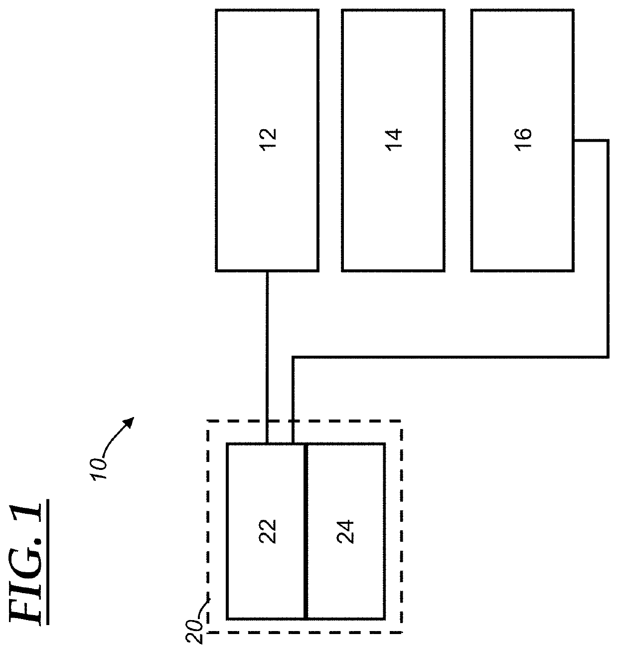
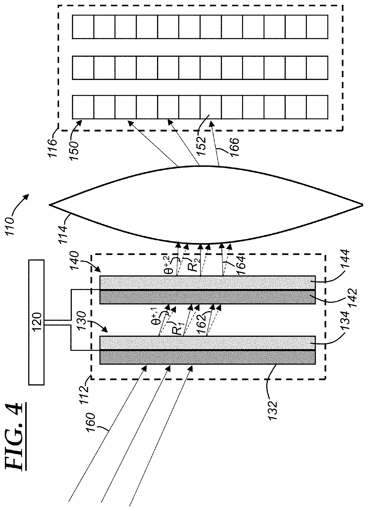
[0044]With reference to FIG. 4, there is shown an electronically-steerable optical sensor 110. The electronically-steerable optical sensor 110 is an example of a solid state image sensor, which is a device that includes an image sensor that is able to obtain different fields of view without mechanically moving parts of the sensor. The electronically-steerable optical sensor 110 includes an electronically-controllable light-steering mechanism 112, optics 114, an image sensor 116, and a controller 120. The light-steering mechanism 112, the optics 114, the image sensor 116, and the controller 120 are analogous to the light-steering mechanism 12, the optics 14, the image sensor 16, and the controller 20 as discussed above, and that discussion is incorporated herein and not repeated for purposes of brevity. The electronically-controllable light-steering mechanism 112 (or “light-steering mechanism 112” for short) includes one or more liquid crystal polarized gratings (LCPGs) and, in the i...

second embodiment

[0049]With reference to FIG. 5, there is shown an electronically-steerable optical sensor 210, which is another example of a solid state image sensor. The electronically-steerable optical sensor 210 includes an electronically-controllable light-steering mechanism 212, optics 214, an image sensor 216, and a controller 220. The light-steering mechanism 212, the optics 214, the image sensor 216, and the controller 220 are analogous to the light-steering mechanism 12, the optics 14, the image sensor 16, and the controller 20 as discussed above and that discussion is incorporated herein and not repeated for purposes of brevity. The electronically-controllable light-steering mechanism 212 (or “light-steering mechanism 212” for short) includes a polarizer 222 and a meta-surface liquid crystal device 224 that includes a meta-surface layer 230 and a liquid crystal layer 240. The liquid crystal layer 240 includes a liquid crystal material (or liquid crystals) that are attached to meta-surface...

third embodiment

[0051]With reference to FIGS. 6-7, there is shown an electronically-steerable optical sensor 310. The electronically-steerable optical sensor 310 includes an electronically-controllable light-steering mechanism 312, optics 314, an image sensor 316, and a controller 320. The light-steering mechanism 312, the optics 314, the image sensor 316, and the controller 320 are analogous to the light-steering mechanism 12, the optics 14, the image sensor 16, and the controller 20 as discussed above and that discussion is incorporated herein and not repeated for purposes of brevity. The electronically-controllable light-steering mechanism 312 (or “light-steering mechanism 312” for short) includes a microelectromechanical systems-based (MEMS-based) device 330 that includes a polarized beam splitter 332, a quarter-waveplate 334, and a MEMS-based scanner (or micro-scanning mirror) 336.

[0052]The polarized beam splitter 332 is a cube- (or cubic-) polarized beam splitter that includes a first right-a...


PUM


Abstract

A system and method for obtaining an overall image that is constructed from multiple sub-images. The method includes: capturing a first sub-image having a first sub-image field of view using an image sensor of an electronically-steerable optical sensor; after capturing the first sub-image, steering light received at the electronically-steerable optical sensor using an electronically-controllable light-steering mechanism of the electronically-steerable optical sensor so as to obtain a second sub-image field of view; capturing a second sub-image having the second sub-image field of view using the image sensor of the electronically-steerable optical sensor; and combining the first sub-image and the second sub-image so as to obtain the overall image.

Description

INTRODUCTION[0001]The exemplary embodiments described herein generally relate to optical sensors such as cameras and, more particularly, to an electronically-steerable optical sensor that can capture images having a field of view that can be electronically controlled.[0002]Vehicles and devices having electronics may come equipped with a variety of sensors and cameras that are mounted on the vehicle, such as a rear-view or forward-view camera. These cameras may be configured to capture a field of view that is relatively wide (e.g., 90°). However, when the field of view is increased in size, the resolution of the camera may be reduced as a trade-off, or other factors may be negatively impacted, such as the price of the camera and / or its various components, the size of the camera, etc. Cameras and / or image sensors used as a part of other, non-vehicle systems experience a similar trade-off of resolution and the breadth of the field of view.[0003]Thus, it may be desirable to provide an i...

Claims


Application Information

Patent Timeline
Patent Type & Authority Applications(United States)
IPC IPC(8): G02B27/28G02B26/08G02B3/00
CPCG02B27/283G02B26/0833G02F2001/133638G05D2201/02G02B3/0006G03B21/006G03B21/142H04N23/54H04N23/55G02B27/286G02F1/29G03B37/02H04N23/58H04N23/698G02F1/133638G02F1/292
Inventor BILIK, IGALPHILIPP, TZVIVILLEVAL, SHAHARSALINGER, JEREMY A.ZENG, SHUQING
Owner GM GLOBAL TECH OPERATIONS LLC
Why Eureka
Try Eureka