Conveyor belt with upright ribs

Active Publication Date: 2021-02-18
CLEAN CONVEYOR BELT BVBA
View PDF0 Cites 1 Cited by
  • Summary
  • Abstract
  • Description
  • Claims
  • Application Information

AI Technical Summary

Benefits of technology

[0006]It is an object of the invention to provide

Problems solved by technology

It is difficult, particularly when the materials comprise small particles, to hold all particles inside the operating zone.
The part

Method used


Image

  • Conveyor belt with upright ribs
  • Conveyor belt with upright ribs
  • Conveyor belt with upright ribs

Examples


Example

[0025]The same or similar elements are designated in the drawing with the same reference numeral.

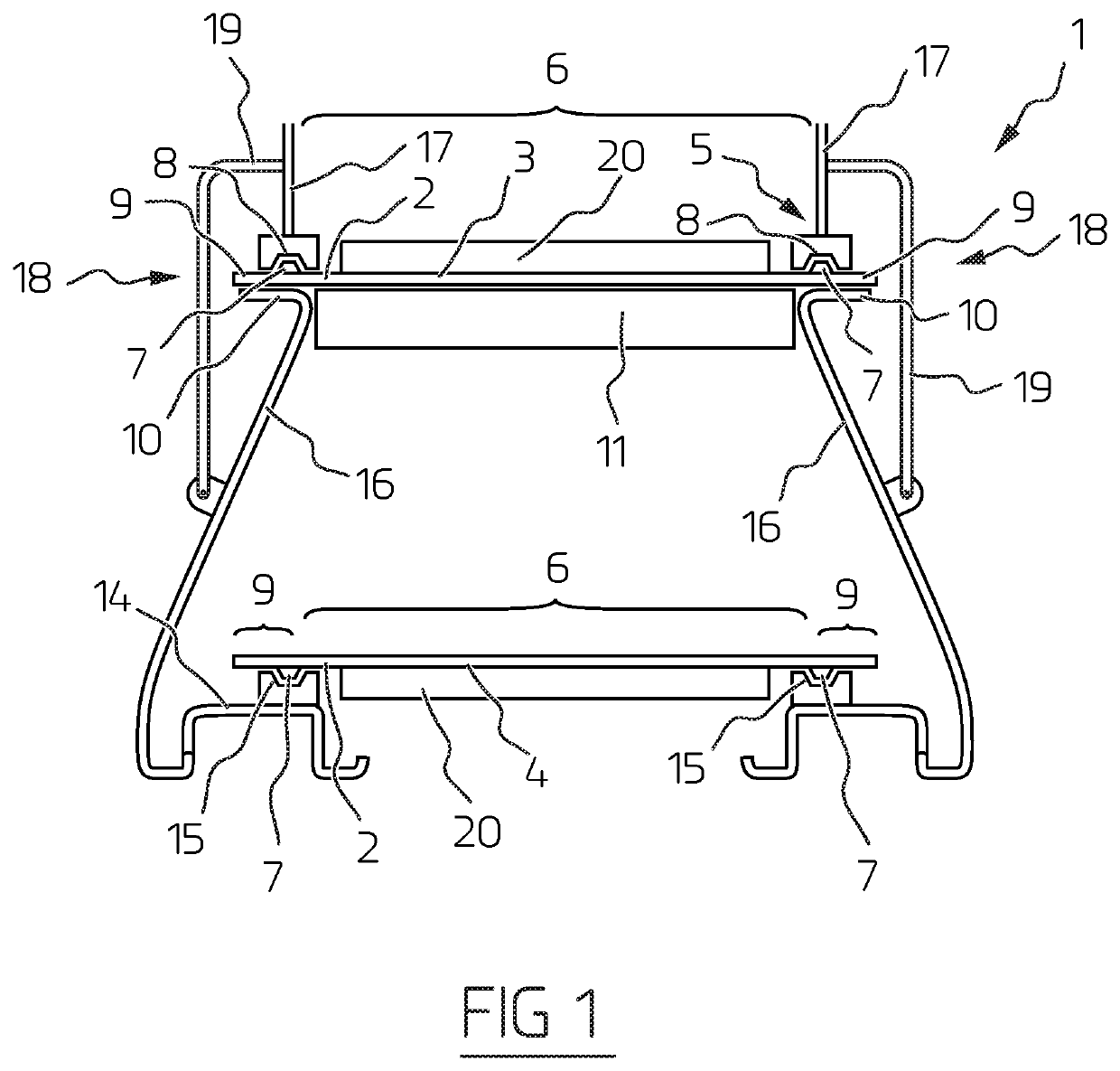
[0026]FIG. 1 shows a cross-section of a conveyor belt system 1 according to a first embodiment of the invention. In this first embodiment the conveyor belt system 1 has a conveyor belt 2 on which an upright rib 7 is formed on either side. The upright ribs 7 demarcate a central zone 6, which central zone 6 forms the primary operating zone of conveyor belt 2. Because conveyor belt 2 is tensioned as endless belt between a first roller and a second roller, the transport side 3 and the return side 4 of conveyor belt 2 are visible in cross-section.

[0027]The transport side 3 is the upper side of conveyor belt 2. Materials are placed on transport side 3, which materials are carried from an inlet to an outlet by movement of conveyor belt 2. This is further described hereinbelow. The materials are placed in the central zone 6 of conveyor belt 2, as seen in transverse direction. This central zone i...


PUM


Abstract

Conveyor belt system with a conveyor belt which extends between a first roller and a second roller so that the conveyor belt has a transport side and a return side, wherein the conveyor belt system further comprises a frame for positioning the conveyor belt, characterized in that the conveyor belt has an upright rib at the position of each of its two transverse ends, which upright ribs extend in the longitudinal direction over substantially the whole conveyor belt, wherein the frame has at the position of the two transverse ends and at least at the position of the transport side a groove in which the upright ribs are received.

Description

BACKGROUND OF THE INVENTIONField of the Invention[0001]The invention relates to a conveyor belt system. The invention relates more specifically to a conveyor belt system for bulk materials.Description of the Related Art[0002]Conveyor belts are much used to move materials between a first location and a second location. The invention relates particularly here to conveyor belts which are adapted to transport bulk materials, also known as bulk cargo or bulk goods. These are materials which are not packed, loaded and transported individually, such as containers, pallets or boxes, but which are deposited in a loading space, processed and transported in bulk. The invention is more particularly optimized for the transport of bulk materials with fine particles. Examples hereof are sand, powder, glass dust. Where the word ‘materials’ is used in the remainder of the description, this is understood to mean bulk materials as described above. The materials comprise multiple particles, grains or p...

Claims


Application Information

Patent Timeline
IPC IPC(8): B65G15/64B65G15/42
CPCB65G15/64B65G15/42B65G15/46B65G21/2081
Inventor GEYSEN, ALEX JEAN
Owner CLEAN CONVEYOR BELT BVBA
Why Eureka
Try Eureka