Axially Compliant Bearing For Precision Positioning

a technology of axial compliant bearings and precision positioning, applied in the direction of bearings, shafts and bearings, rolling contact bearings, etc., can solve the problems of limiting the usefulness of rolling bearing guided stages in practice, affecting the precision and speed of rolling contact bearings, and hampering the quality of manufactured products, so as to reduce rms error, reduce friction, and ensure continuous roll-to-roll manufacturing high precision

Active Publication Date: 2021-02-18
RGT UNIV OF MICHIGAN +1
View PDF0 Cites 3 Cited by
  • Summary
  • Abstract
  • Description
  • Claims
  • Application Information

AI Technical Summary

Benefits of technology

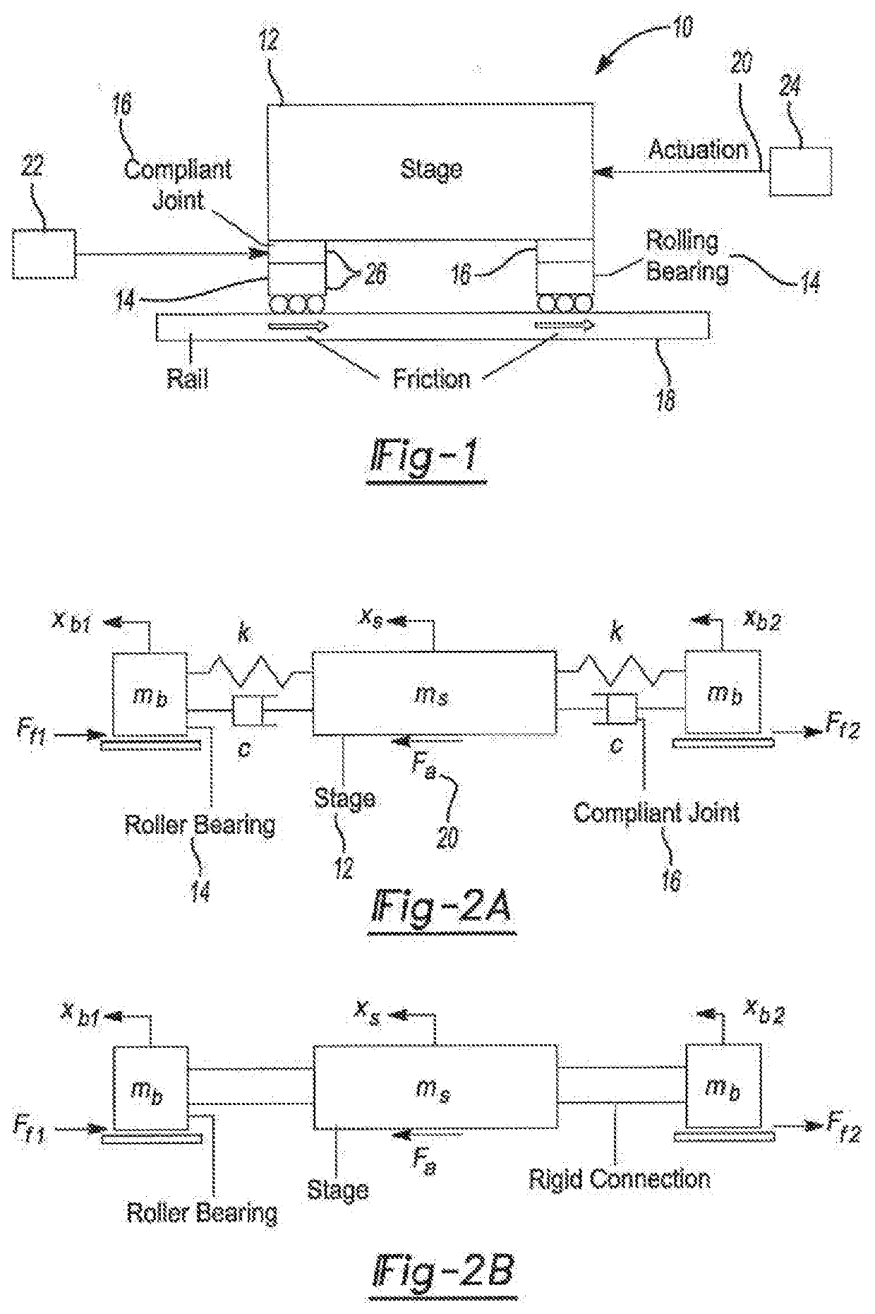
[0004]Precision motion stages are designed for precise positioning in various manufacturing processes. Among the bearing options for precision stages, rolling bearings are the most cost effective, especially for applications requiring large motion range and vacuum compatibility. However, the presence of nonlinear friction adversely affects the precision and speed of rolling bearing guided stages. The state of art in addressing this problem is to perform model-based friction compensation, which suffer from robustness problems, thus limiting their usefulness in practice. This invention addresses the problem of nonlinear effect of friction in rolling bearing guided stages by using compliant joint(s) to provide a simple, model-free and potentially low-cost approach.
[0124]According to the present teachings, a novel rotary servo system for achieving high precision continuous roll-to-roll manufacturing has been provided. The present system integrates a rotary compliant joint 120 (friction isolator (FI)), a mechanical component, to mitigate the undesirable effects of friction on the tracking performance of the processing roller 116 during constant velocity motions, thus improving the quality of the manufactured products. It has been demonstrated through frequency domain analysis that rotary compliant joint 120 improves the disturbance rejection ability of the system by low-pass filtering the frictional disturbance of the supporting bearings. It has been demonstrated in experiments that the compliant joint rotary system achieves up to 61% reductions in RMS tracking error during CV motions of different speed, compared to a conventional rotary system.

Problems solved by technology

However, the presence of nonlinear friction adversely affects the precision and speed of rolling bearing guided stages.
The state of art in addressing this problem is to perform model-based friction compensation, which suffer from robustness problems, thus limiting their usefulness in practice.
However, broadband frictional disturbances caused by the guiding ball bearings affect the precision of the processing roller 116 in the roll-to-roll system, severely hampering the quality of the manufactured products.
Conventional feedback control techniques encounter difficulties in mitigating the broadband frictional disturbances.

Method used


Image

  • Axially Compliant Bearing For Precision Positioning
  • Axially Compliant Bearing For Precision Positioning
  • Axially Compliant Bearing For Precision Positioning

Examples


Embodiment Construction

[0037]Example embodiments will now be described more fully with reference to the accompanying drawings.

[0038]Example embodiments are provided so that this disclosure will be thorough, and will fully convey the scope to those who are skilled in the art. Numerous specific details are set forth such as examples of specific components, devices, and methods, to provide a thorough understanding of embodiments of the present disclosure. It will be apparent to those skilled in the art that specific details need not be employed, that example embodiments may be embodied in many different forms and that neither should be construed to limit the scope of the disclosure. In some example embodiments, well-known processes, well-known device structures, and well-known technologies are not described in detail.

[0039]The terminology used herein is for the purpose of describing particular example embodiments only and is not intended to be limiting. As used herein, the singular forms “a,”“an,” and “the” ...


PUM


Abstract

A rotationally compliant bearing roller assembly having a roller, at least one bearing member operably coupled to a base configured to support rotational movement about a rotational axis; and a rotary compliant joint interconnecting the at least one bearing member to the roller. The rotary compliant joint having a first compliance in a rotational direction about the rotational axis to permit movement of the roller in the rotational direction relative to the at least one bearing member, such that the first compliance being greater than a friction induced compliance of the at least one bearing member in the rotational direction. The compliant joint having a second compliance in a direction orthogonal to the rotational direction, such that the second compliance being less than the first compliance.

Description

CROSS-REFERENCE TO RELATED APPLICATIONS[0001]This application is a continuation-in-part of U.S. patent application Ser. No. 15 / 772,952 filed on May 2, 2018, which is a National Stage of International Application No. PCT / US2016 / 060033 filed on Nov. 2, 2016, which claims the benefit of U.S. Provisional Application No. 62 / 249,589, filed on Nov. 2, 2015. The entire disclosure of the above applications are incorporated herein by reference.FIELD[0002]The present disclosure relates to a motion system and, more particularly, relates to a motion stage equipped with an axially compliant rolling bearing and / or a rotary system equipped with a rotary compliant system.BACKGROUND AND SUMMARY[0003]This section provides background information related to the present disclosure which is not necessarily prior art. This section provides a general summary of the disclosure, and is not a comprehensive disclosure of its full scope or all of its features.[0004]Precision motion stages are designed for precis...

Claims


Application Information

Patent Timeline
Patent Type & Authority Applications(United States)
IPC IPC(8): F16C32/04
CPCF16C32/0442F16C27/04F16C27/00F16C2233/00F16C2210/06F16C2326/00F16F15/02
Inventor OKWUDIRE, CHINEDUM E.DONG, XINKANG, DONGWOO
Owner RGT UNIV OF MICHIGAN
Why Eureka
Try Eureka