
Motor and Drive Circuit and Driving Method the Same

a technology of motor and drive circuit, applied in the direction of propulsion system, mechanical energy handling, electronic commutators, etc., can solve the problems of increasing the burden on the environment, heavy machines, and only providing power in one dimension for traditional power units such as motors, so as to achieve dramatic reduction of environmental burden and the weight of machines

Active Publication Date: 2021-02-18
TENSOR TECH CO LTD
View PDF0 Cites 7 Cited by
  • Summary
  • Abstract
  • Description
  • Claims
  • Application Information

AI Technical Summary

Benefits of technology

The patent describes a motor that uses three stators to create a superimposed magnetic field that allows the rotor to rotate in multiple directions without needing an extra drive part. This results in multi-dimensional operations and reduces the weight and environmental burden of machines.

Problems solved by technology

However, traditional power units, such as motors, can only provide power in one dimension.
Therefore, it is necessary to configure multiple motors to complete multi-dimensional operation of precision machines, which makes the machines heavy.
As the total weight of the machines increases, more energy is required for the operation or execution of the machines, and energy consumption increases.
In addition, more components mean that the manufacture of machines has a greater burden on the environment accordingly.
Therefore, how to enable motors to provide power in multiple dimensions to reduce the weight of machines, reduce power consumption, and reduce material consumption so as to reduce environmental burden has become an important issue.

Method used


Image

  • Motor and Drive Circuit and Driving Method the Same
  • Motor and Drive Circuit and Driving Method the Same
  • Motor and Drive Circuit and Driving Method the Same

Examples


Embodiment Construction

[0036]The method and the drive circuit and driving method of the same in the preferred embodiments of this disclosure are described below with reference to the relevant drawings, and identical components are explained with identical reference signals.

[0037]It is important to note that all directional terms in the embodiments of this disclosure (such as upper, lower, left, right, front, and back) are used only to explain the relative positional relationship, movement condition, and the like between components in a particular state (as shown in the accompanying drawings), and if the particular state changes, the directional terms will change accordingly.

[0038]The motor 1 in this embodiment may be applied to, but is not limited to, machines such as vehicles, small satellites, unmanned underwater vehicles, and unmanned aerial vehicles.

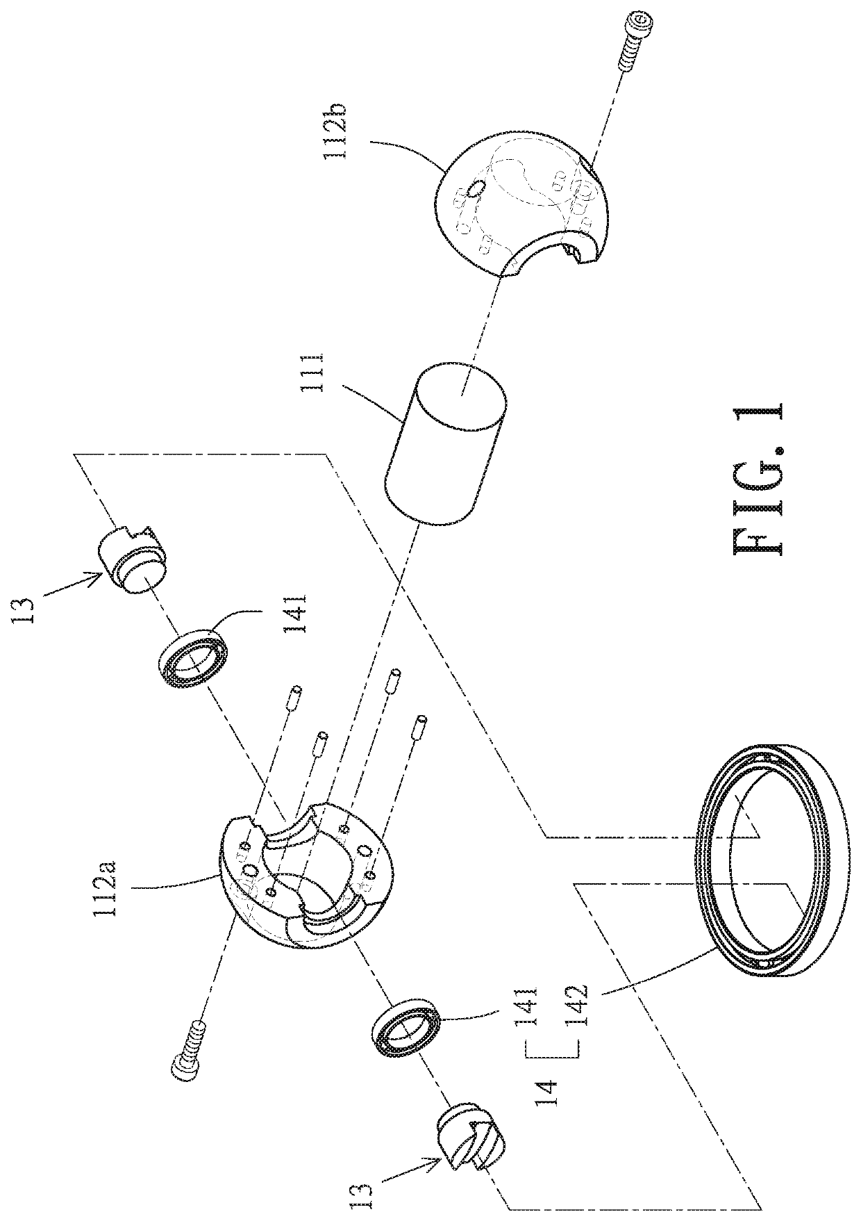
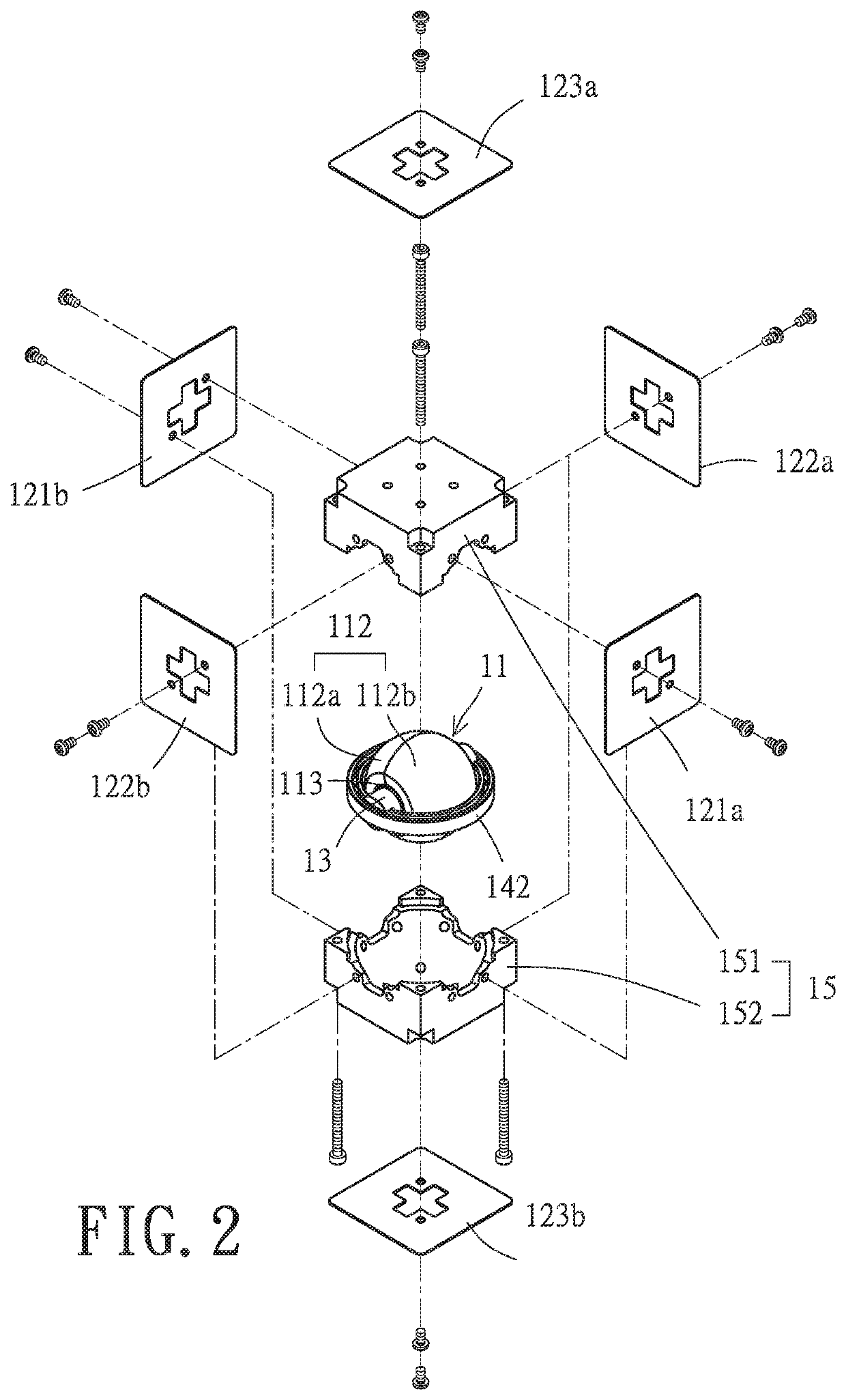
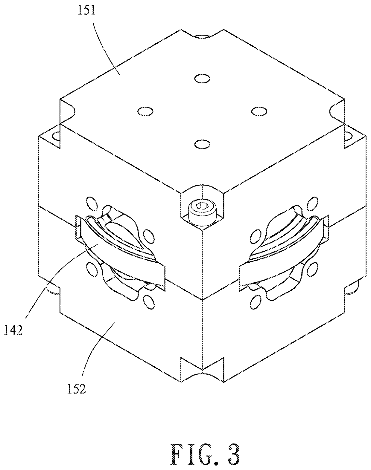
[0039]As shown in FIGS. 1-3 and 5, the motor 1 in this disclosure comprises stators 12(see FIG. 5, stators 12 means that all the stator coils for example ...


PUM


Abstract

A motor comprising a stator and a rotor; the stator includes a first stator, a second stator, and a third stator; the stators each include at least one stator coil; the rotor includes a magnetic element, a first bearing, a second bearing, and a shaft; the stators generating a superimposed magnetic field together causes the magnetic element to rotate; when the magnetic element rotates in the first plane, the outer ring of the first bearing rotates; the center of the first bearing is located in a plane where the second bearing is located, and when the magnetic element rotates in the second plane, the inner ring of the second bearing rotates; the central axis of the shaft passes through the center of the first bearing; wherein the shaft is rotatably fixed to the first bearing and connected to the second bearing; the magnetic element located in where the central axis of the first bearing meets the central axis of the second bearing, the normal vector of the first plane is parallel to the axial direction of the shaft; the normal vector of the second plane is perpendicular to the axial direction of the shaft.

Description

BACKGROUND OF THE INVENTION1. Technical Field[0001]This disclosure relates to a motor and a drive circuit and driving method of the same, in particular to a ball motor that can perform control in more than two dimensions without configuring actuators or drive components for each dimension, and a drive circuit and driving method of the motor.2. Description of Related Art[0002]“Force” is a vector, and the transmission direction of the force is traditionally changed by means of components such as pulleys, gears, screws, cams, or connecting rods, or the combination of these components.[0003]With the advances of technology, the combination of multiple actuators or drives and the force applied to the proper position and in the proper direction are generally necessary to realize the operation of precision machines (such as small satellites, robotic arms) in multiple dimensions.[0004]However, traditional power units, such as motors, can only provide power in one dimension. Therefore, it is ...

Claims


Application Information

Patent Timeline
IPC IPC(8): H02K41/06H02K3/26H02K7/08H02K11/215H02K11/33H02P6/17H02P6/30
CPCH02K41/065H02K3/26H02K7/08H02K2203/03H02K11/33H02P6/17H02P6/30H02K11/215H02K2201/18H02K7/088H02K16/02H02K7/02H02P6/08Y02E60/16
Inventor YEN, PO-HSUNLEE, SHANG-JUNGCHANG, YUNG-CHENGHOU, SUNG-LIANG
Owner TENSOR TECH CO LTD
Learn More