Active brake locking system

a technology of active brakes and locking systems, which is applied in the direction of braking systems, automatic initiations, transportation and packaging, etc., can solve the problems of unauthorized individuals being able to access and deprive the owner of the use of the vehicle, severe damage to the vehicle or stripping, and being sold for parts

Pending Publication Date: 2021-02-25
FRAWLEY PATRICK JOSEPH +1
View PDF3 Cites 1 Cited by
  • Summary
  • Abstract
  • Description
  • Claims
  • Application Information

AI Technical Summary

Benefits of technology

[0015]In some embodiments, the flow of fluids within the existing vehicle system controls operation of the clutch, wherein the clutch is in communication with the engine, wherein the clutch prevents translation of rotational movement from the engine to one or more wheels.
[0027]Preferably in another embodiment the flow of fluids within the existing vehicle system controls operation of the clutch, wherein the clutch is in communication with the engine, wherein the clutch prevents translation of rotational movement from the engine to one or more wheels.
[0035]Preferably in one embodiment said hydraulic system is the brake hydraulic system, and when said actuator has actuated to close said first flow valve, said flow through said second check valve in a single direction allows for the brakes of said vehicle to prevent rotation of at least one wheel of said vehicle.
[0036]Preferably in another embodiment said hydraulic system is the clutch hydraulic system controlling the operation of the clutch of the vehicle which is in communication with engine of said vehicle, and when said actuator has actuated to close said first flow valve, said flow through said second check valve in a single direction preventing modulation of the communication between said engine and said clutch.
[0044]Preferably said hydraulic system is the brake hydraulic system, and when said actuator has actuated to close said first flow valve, said flow through said second check valve in a single direction allows for the brakes of said vehicle to prevent rotation of at least one wheel of said vehicle, and said brakes remain engaged so long as said first flow valve remains closed.

Problems solved by technology

While insurance may exist to reimburse the loss, it is often at a fraction of the vehicle's value and is generally accompanied by significant amount of actions necessary from the vehicle owner to the insurance company.
While these manufactured protections are usually standard, they are antiquated as evidenced by the large number of vehicle thefts yearly.
Whether an unauthorized individual would break a locking mechanism to gain access, fabricate a universal or “slam” key, steal the original keys from the vehicle owner, or forcibly take the car from the owner's concurrent possession, unauthorized individuals are able to access and deprive the owner from the use of the vehicle.
Alternative outcomes include the vehicle having been severely damaged or stripped and sold for parts.
Passive locking systems, as described above may prevent or create and obstacle for someone to gain unauthorized access, but they fail to prevent use of the vehicle after unauthorized access has occurred.
Impact to the rear of the vehicle by a pursuit vehicle, shooting a target mounted on the vehicle or sending a signal from a remote control can all result in the fluid pressures in the braking system of the vehicle being modified so that the vehicle is stopped and rendered temporarily inoperable.
Neither of the above examples allow for the remote communication and control of the braking system by the owner or other authorized controlling parties.
Again, having to control the braking system from within the vehicle may only provide a momentary addition to the time needed by a thief or hijacker from being able to operate the vehicle.

Method used


Image

  • Active brake locking system
  • Active brake locking system
  • Active brake locking system

Examples


Embodiment Construction

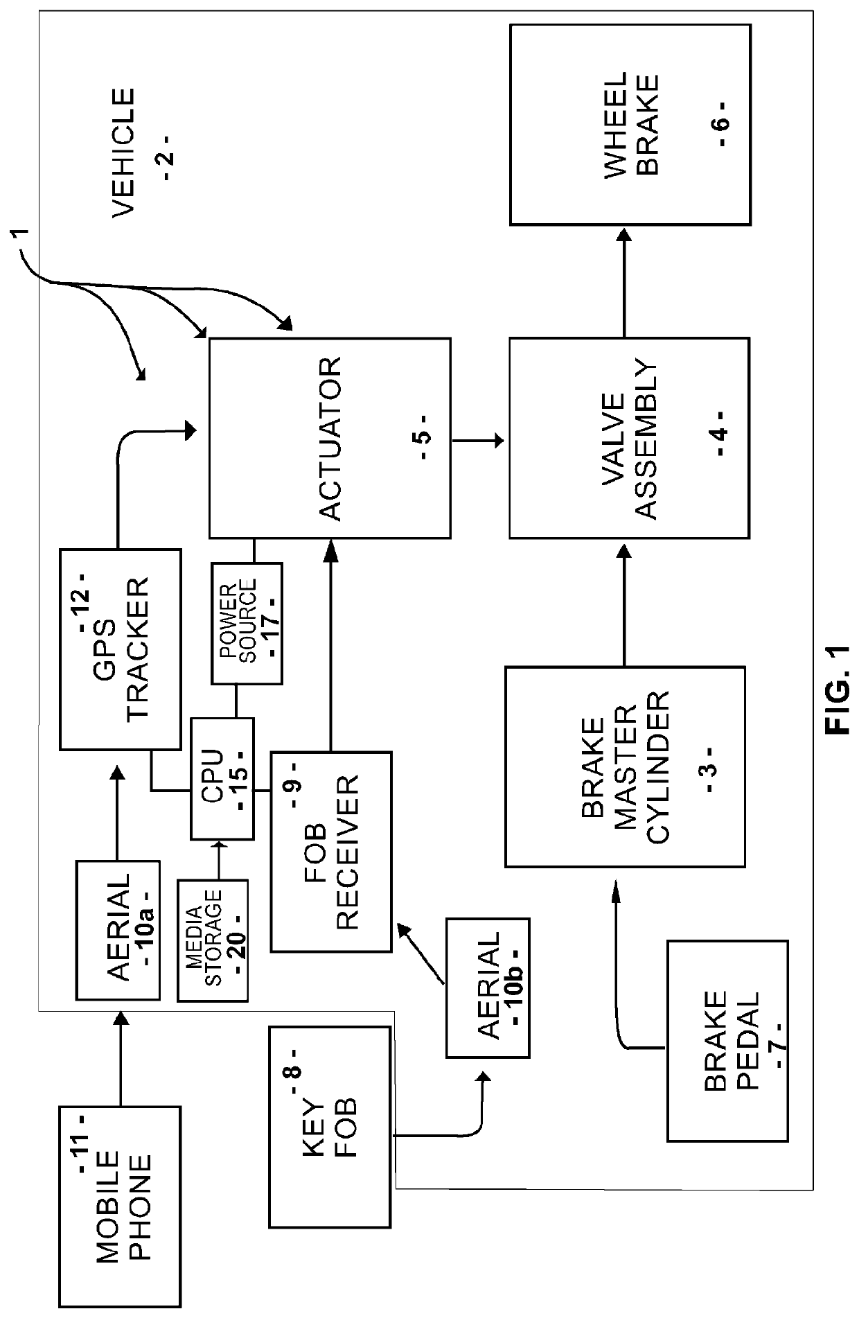
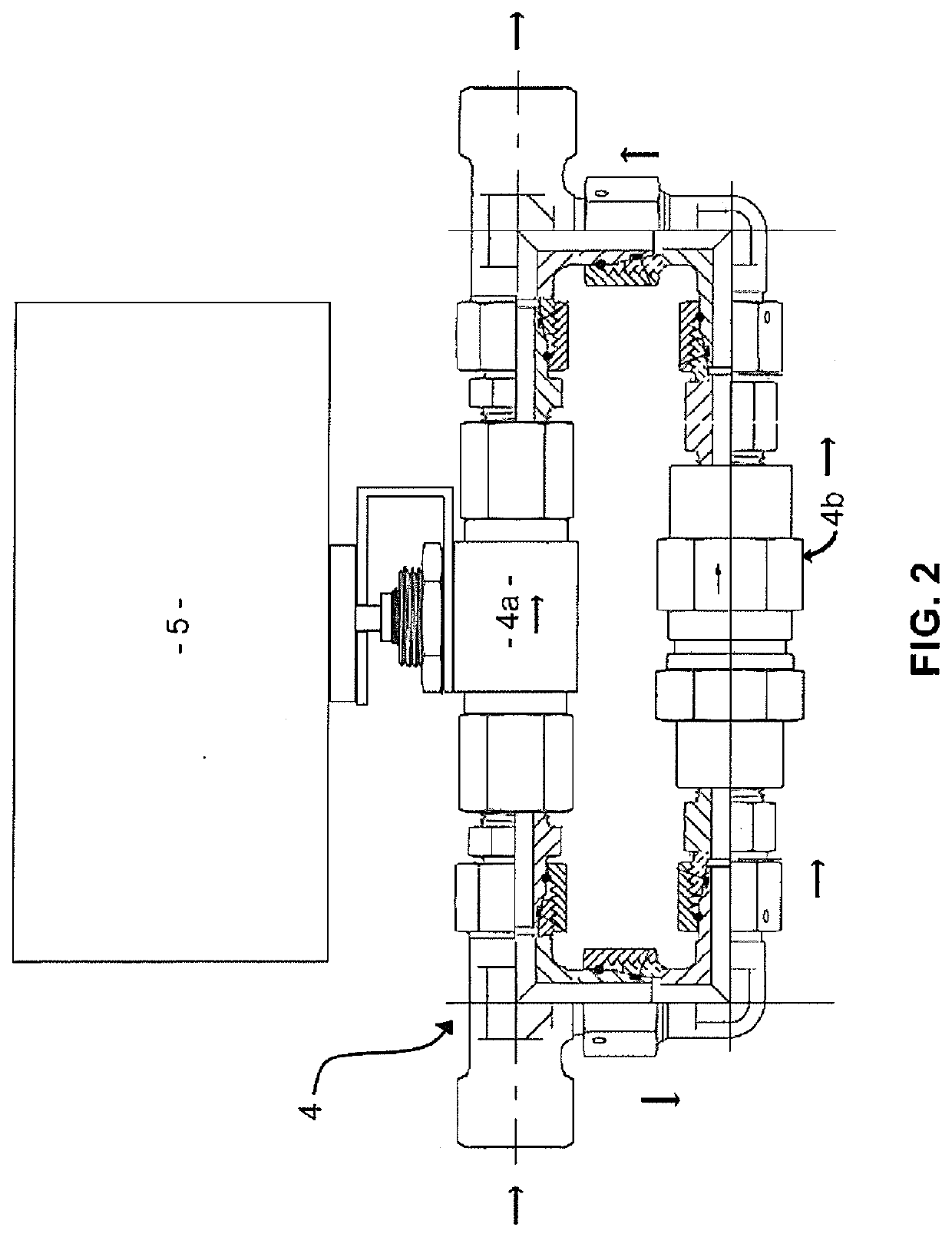
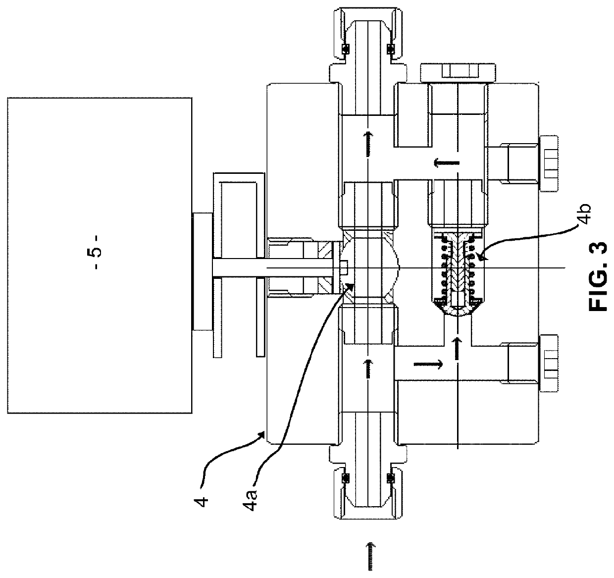
[0053]Preferred embodiments of the present invention and their advantages may be understood by referring to FIGS. 1 to 3.

[0054]Embodiments of the invention are discussed below with reference to the Figures. However, those skilled in the art will readily appreciate that the detailed description given herein with respect to these figures is for explanatory purposes as the invention extends beyond these limited embodiments. For example, it should be appreciated that those skilled in the art will, in light of the teachings of the present invention, recognize a multiplicity of alternate and suitable approaches, depending upon the needs of the particular application, to implement the functionality of any given detail described herein, beyond the particular implementation choices in the following embodiments described and shown. That is, there are numerous modifications and variations of the invention that are too numerous to be listed but that all fit within the scope of the invention. Al...


PUM


Abstract

An active brake locking system has one or more valves in communication with an existing hydraulic vehicle system; one or more actuators controlling operation of the one or more valves; and a power source electrically connected to one or more processors and a media storage device, wherein the one or more actuators control a flow of fluids within the existing vehicle system.

Description

BACKGROUND OF THE INVENTION1. Field of Invention[0001]The present invention relates to the field of hydraulic locking systems, and more particularly to a hydraulic locking system for an automotive brake assembly.2. Description of Related Art[0002]A vehicle can be a substantial financial investment. Accordingly, protection against theft is crucial to prevent loss. While insurance may exist to reimburse the loss, it is often at a fraction of the vehicle's value and is generally accompanied by significant amount of actions necessary from the vehicle owner to the insurance company.[0003]Rather than rely on subsequent remedial measures to compensate the vehicle owner in the case of loss of the vehicle, people generally implement certain measures to prevent the loss from occurring. Vehicles are generally manufactured with locking mechanisms to prevent access from unauthorized individuals to the interior of the vehicle. Further, the ignition and starting process of the vehicle is generally...

Claims


Application Information

Patent Timeline
Patent Type & Authority Applications(United States)
IPC IPC(8): B60T13/66B60R25/08B60T7/16B60T13/68B60T17/16B60R25/33
CPCB60T13/662B60R25/08B60T7/16B60R2325/207B60T17/16B60R25/33B60T13/686B60T7/12
Inventor KIRBY, STEVEN JAMES
Owner FRAWLEY PATRICK JOSEPH
Why Eureka
Try Eureka