Bushing assembly

a technology of assembly and bar stock, which is applied in the field of cutting machines, can solve the problems of cnc machine users experiencing delays in manufacturing, the process of changing bushings can be costly and time-consuming, and the bushings may not be able to support the bar stock along its entire length, so as to increase the effective work area, facilitate the inserting and removal, and facilitate the effect of changing the bar stock

Inactive Publication Date: 2021-02-25
RAPID RACE CARS INC
View PDF7 Cites 0 Cited by
  • Summary
  • Abstract
  • Description
  • Claims
  • Application Information

AI Technical Summary

Benefits of technology

[0010]An advantage of the present invention is that the sleeve of the bushing assembly is easily insertable and removable from the guide member which accordingly allows a user to easily and efficiently change bar stocks.
[0011]Another advantage of the present invention is that the sleeve of the bushing assembly increases a support area of the bushing assembly which in turn increases the effective work area on the bar without interrupting a machining process to reposition the bar stock.
[0012]Yet another advantage of the present invention is that the sleeve of the bushing assembly allows a user to run a looser fit between the sleeve and bar stock in order to accommodate clearance difference among various bar stocks.

Problems solved by technology

The process of changing bushings can be costly and time-consuming.
Also, a user of a CNC machine may experience delays in manufacturing because the user may need to order a unique bushing from a tool supplier in order to machine a correspondingly sized bar stock.
Often, due to the structural connection between the bushing and the headstock, the bushing may not be capable of supporting the bar stock along its entire length.
In such cases, the ability of the bushing to support the bar stock may limit the seamless or uninterrupted work area of the bar stock.

Method used


Image

  • Bushing assembly
  • Bushing assembly
  • Bushing assembly

Examples


Embodiment Construction

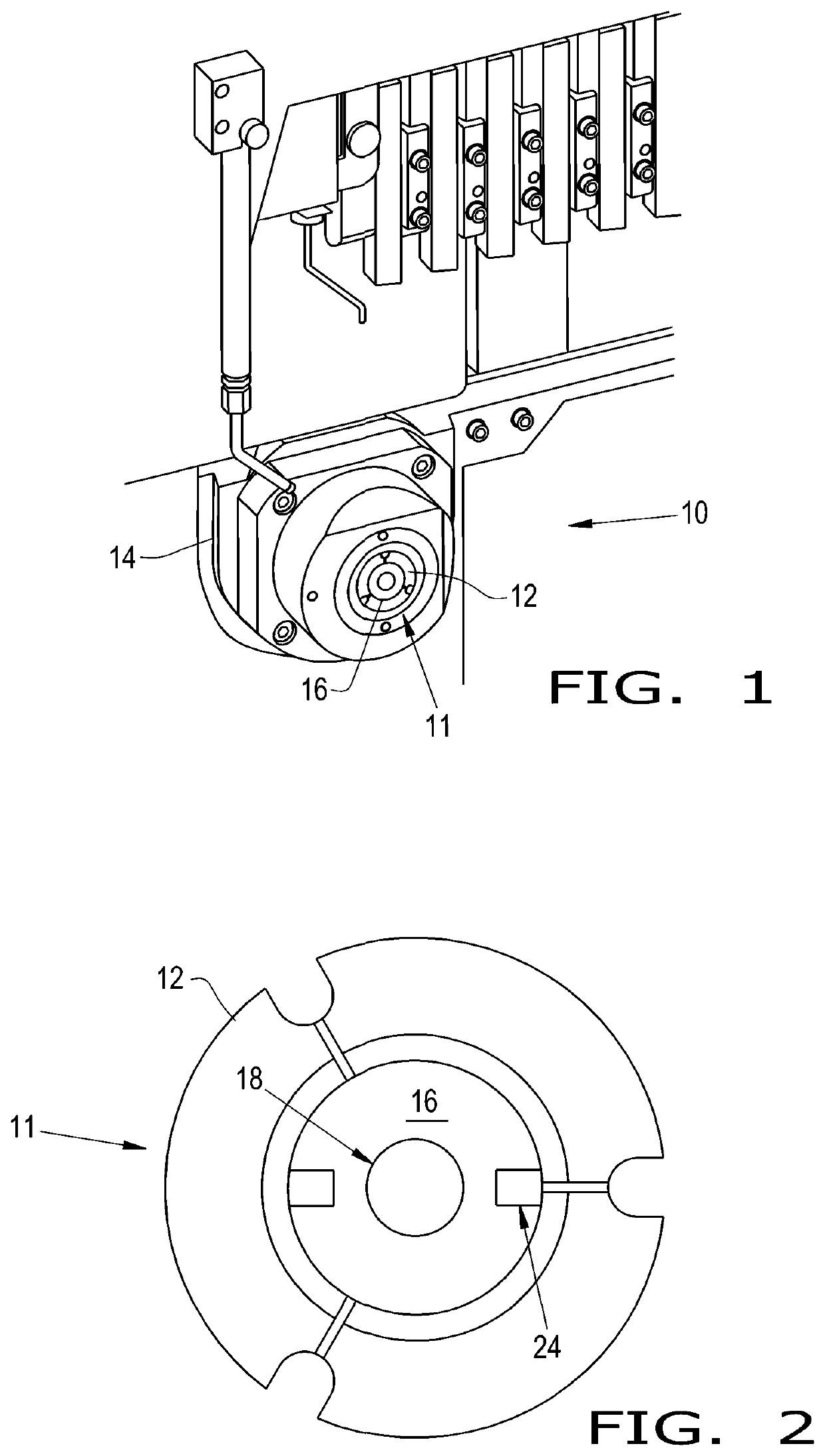
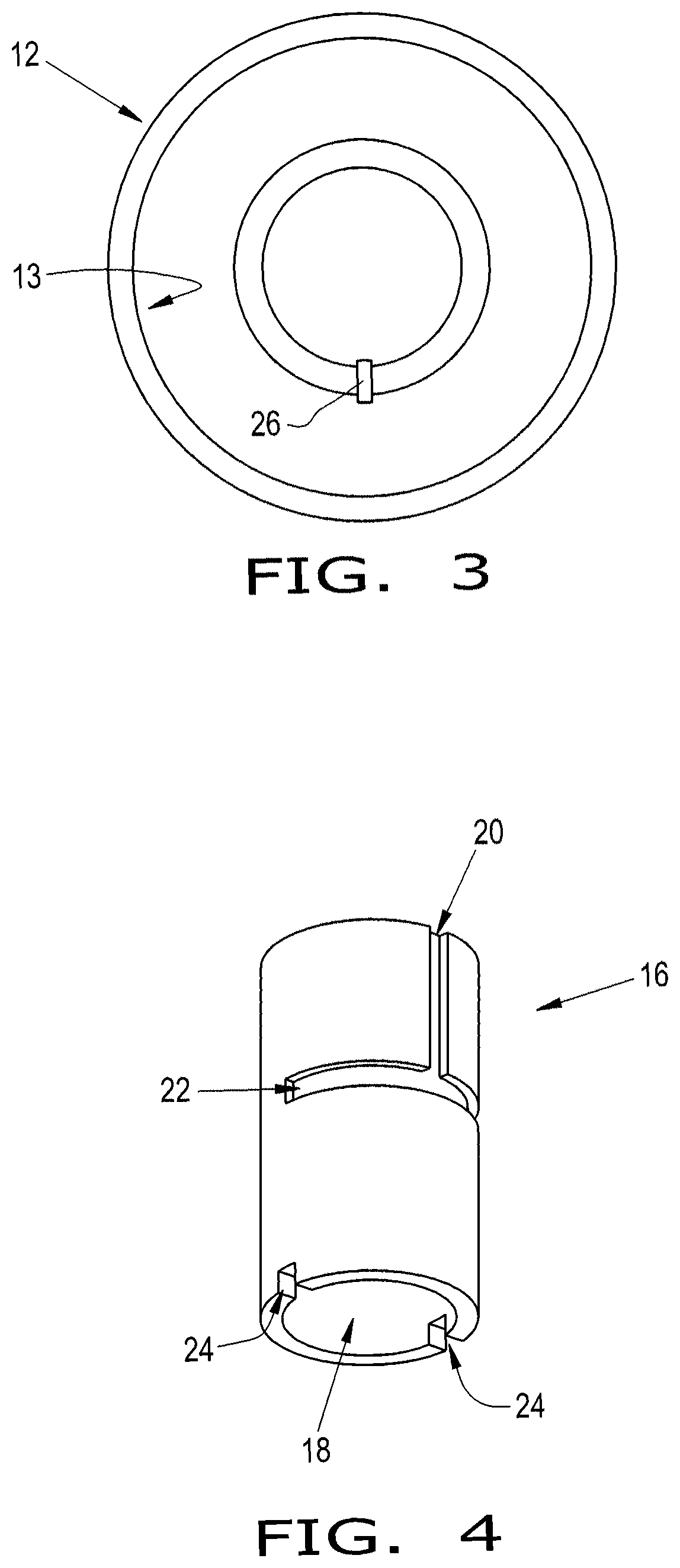
[0023]Referring now to the drawings, and more particularly to FIGS. 1-4, there is shown a cutting machine 10 in the form of a Swiss machine 10 that has a bushing assembly 11. The Swiss machine 10 also includes one or more cutting tools for machining the bar stock.

[0024]The bushing assembly 11 includes a guide member 12, which is arranged in a headstock 14 of the Swiss machine 10, and a sleeve 16, which is inserted into the guide member 12. The bushing assembly 11 is connected to the headstock 14 via the guide member 12 being arranged in the headstock 14. The bushing assembly 11 supports and holds the bar stock, which is fed through the sleeve 16.

[0025]The guide member 12 may be a collet or a bushing 12. The collet or bushing 12 may be referred to as alternates to one another herein. Even though bushings and collets are distinct from each other, for purposes of describing the invention, they serve the purpose of retaining the sleeve 16 therein through which bar stock is fed and suppo...


PUM

PropertyMeasurementUnit
lengthaaaaaaaaaa
lengthaaaaaaaaaa
lengthaaaaaaaaaa

Abstract

A cutting machine for machining a bar stock that includes at least one cutting tool, a headstock, and a bushing assembly connected to the headstock. The bushing assembly includes a guide member that includes a body having at least one bore therein and at least one guide mating feature. The bushing assembly further includes a sleeve removably inserted within the at least one bore of the body of the guide member. The sleeve includes a body having a bore therein and at least one sleeve mating feature. The bore of the sleeve is configured for supporting and holding the bar stock. The at least one sleeve mating feature is engaged with the at least one guide mating feature for retaining the sleeve within the guide member.

Description

CROSS REFERENCE TO RELATED APPLICATIONS[0001]This is a non-provisional application based upon U.S. provisional patent application Ser. No. 62 / 889,256, entitled “GUIDE BUSHING SLEEVE”, filed Aug. 20, 2019, which is incorporated herein by reference.BACKGROUND OF THE INVENTION1. Field of the Invention[0002]The present invention relates to cutting machines, and, more particularly, to a bushing assembly for a cutting machine.2. Description of the Related Art[0003]Swiss machining refers to the use of machines that use bar stock of specific dimensions that is fed through a headstock to effectively repeatably manufacture parts from the bar stock. These Swiss machines typically are 3-9 axis multi-axis Computer Numerical Control (CNC) machines that combine CNC machines with Autoloaders, CNC swiss screw machines, and Twin Spindle lathes. The Swiss machining process uses an assortment of shaping tools and spindles that enable operators to carry out a number of different procedures.[0004]For man...

Claims


Application Information

Patent Timeline
Patent Type & Authority Applications(United States)
IPC IPC(8): F16C17/02F16C33/06B23Q5/04
CPCF16C17/02F16C2322/00B23Q5/04F16C33/06B23B13/02B23B2260/026B23B2260/042B23B2260/072B23B31/20F16C33/08
Inventor MARCKEL, JR., LAWRENCE R.MARCKEL, RONDADUNCAN, TROY L.
Owner RAPID RACE CARS INC
Why Eureka
Try Eureka