Modular and collapsible chair for children and method thereof
- Summary
- Abstract
- Description
- Claims
- Application Information
AI Technical Summary
Benefits of technology
Problems solved by technology
Method used
Image

Examples
Embodiment Construction
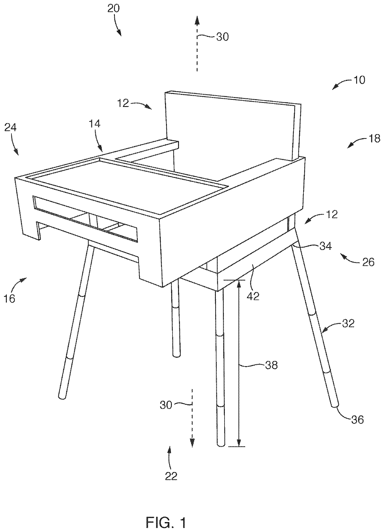
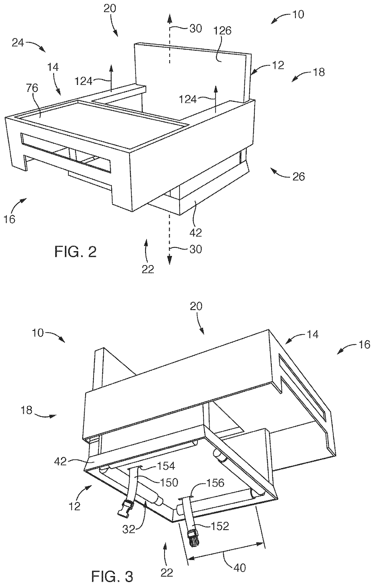
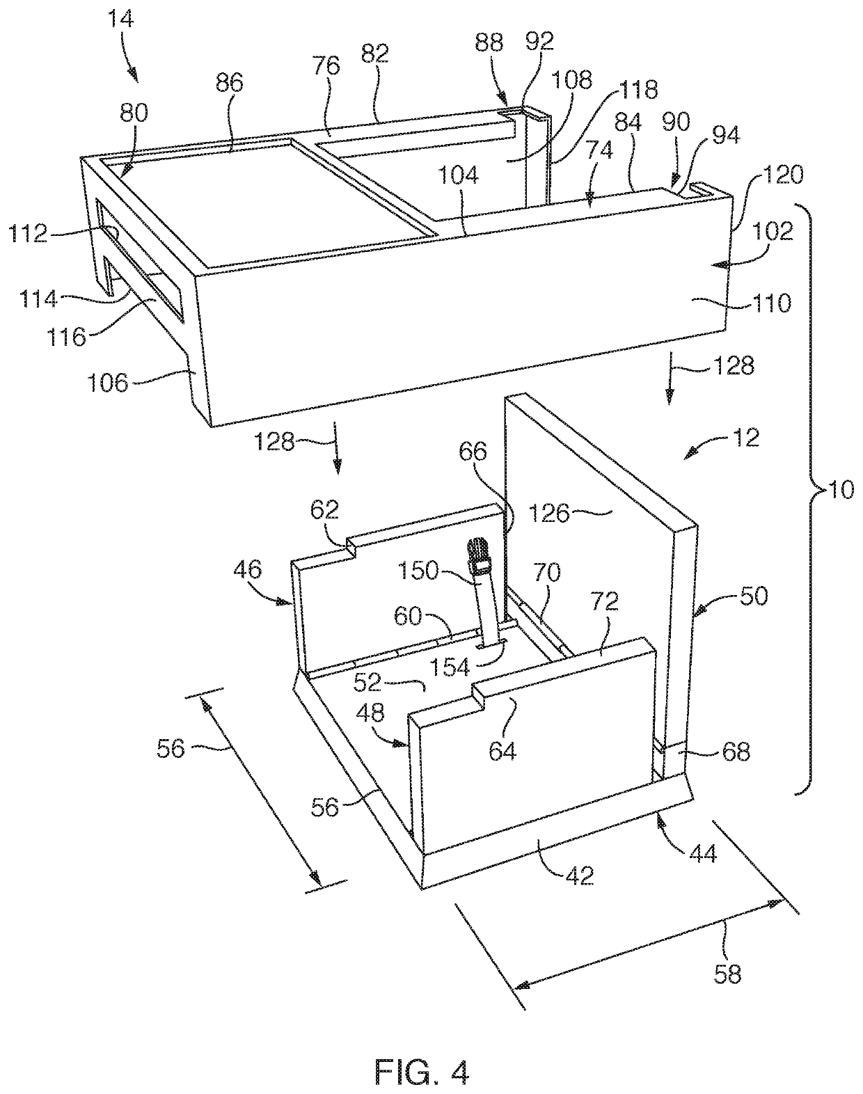
[0026]Referring first to FIGS. 1-3, a modular chair 10 having modular components of a seat portion 12 and a tray portion 14 is provided. The modular chair 10 of the present invention may be employed as a “high chair” sized and configured to provide a safe seating arrangement for a child. Further, the modular chair 10 includes functionality that facilitates the modular chair 10 to be readily disassembled by separating the tray portion 14 from the seat portion 12, and then moving components of the modular chair 10 to one or more compact positions (see, e.g., FIGS. 10 and 11). The modular chair 10 is therefore highly portable so as to be easily moved from one location to another or stored on, for example, a shelf in a closet or stored in a vehicle with a minimally sized footprint.
[0027]The modular chair 10 may be positioned in a use state and a non-use compact state. In the use state, the tray portion 14 may be vertically and slidingly positioned over and with the seat portion 12 such ...
PUM
 Abstract
Description
Claims
Application Information