
Route-based directional antenna

a directional antenna and route technology, applied in the direction of antennas, antenna details, antenna adaptation in movable bodies, etc., can solve the problems of adding complexity to the optimal direction along the route, and achieve the effect of optimizing the data connection, and optimizing the signal strength or signal quality

Active Publication Date: 2021-03-04
MIWIRE APS
View PDF0 Cites 5 Cited by
  • Summary
  • Abstract
  • Description
  • Claims
  • Application Information

AI Technical Summary

Benefits of technology

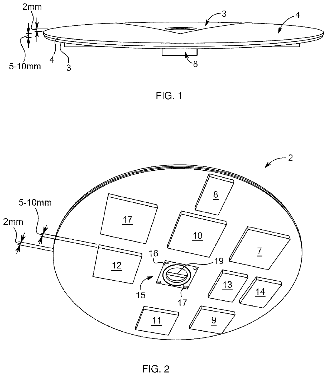
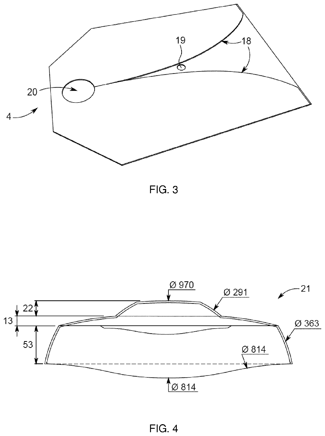
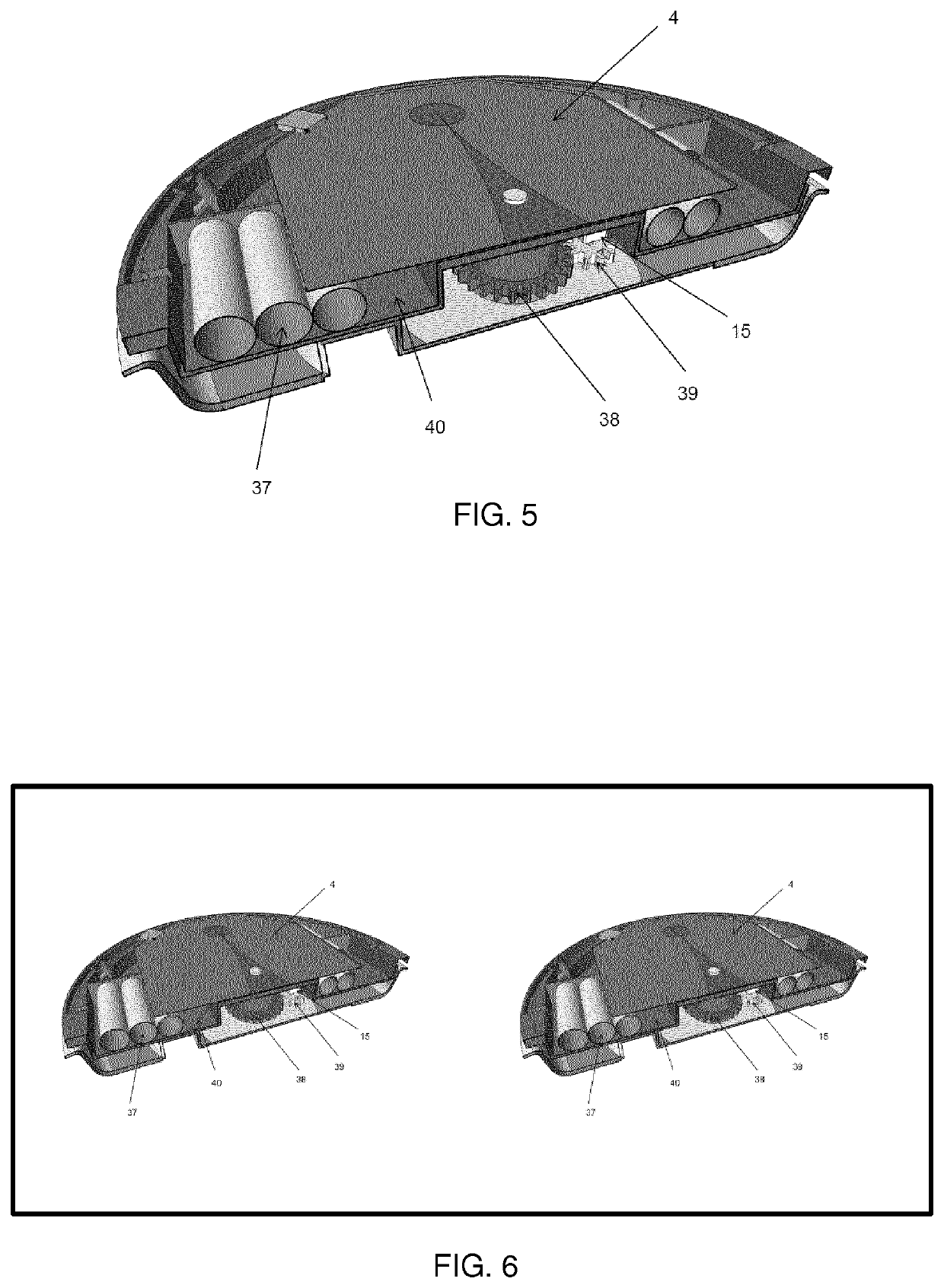
The present patent relates to an antenna device for vehicles that optimizes signal strength or quality from a mobile network. The device uses a directional antenna that needs to be pointed towards a fixed transceiver to achieve the strongest signal. The device can be mounted on a vehicle and can be used in an existing mobile network without modifying it. The device can also dynamically scan the environment and adjust its orientation based on the vehicle's direction of travel and the position of the fixed transceivers. The device can be used in a variety of vehicles, such as cars, boats, or ferries. The technical effect of this patent is to improve the signal strength or quality of a mobile network in a moving vehicle and ensure a seamless connection along the route.

Problems solved by technology

This may add complexity to the optimal direction along the route.

Method used


Image

  • Route-based directional antenna
  • Route-based directional antenna
  • Route-based directional antenna

Examples


examples

[0076]An example of the use of one embodiment of the present invention may be given with reference to FIG. 7 illustrating the situation on a map. A car equipped with one embodiment of the present invention starts in position 1, where it has the following connections to transceivers:[0077]Omni-directional antenna 0 connected to a transceiver through connection A with 800 MHz and −85 dBm.[0078]Directional antenna 1 connected to a transceiver through connection B with 2600 MHz and −98 dBm.[0079]Directional antenna 2 connected to a transceiver through connection C with 2100 MHz and −96 dBm.

[0080]The omni-directional antenna 0 is also listening for a signal from transceiver E, but the signal strength is too low at position 1. The destination at position B has been entered into the navigation system in the car or transferred form a mobile device to the car. A database shows that there is a transceiver working at a frequency of 1800 MHz with good coverage in the area that the car is moving...


PUM


Abstract

The present disclosure relates to an antenna device for a vehicle for optimizing the signal strength or quality from a mobile network having at least one fixed transceiver. The device comprises: at least one directional antenna; at least one turning device, such as an electric motor, for rotating the directional antenna around an axis substantially perpendicular to the antenna boresight; and a microprocessor configured to calculate an azimuthal rotation angle for pointing the directional antenna to at least one selected fixed transceiver. The calculated azimuthal rotational angle is based on: directional and positional data of the vehicle; positional data of the selected fixed transceivers; and a route for navigating the vehicle between a starting point and a destination. The azimuthal rotation angle of the directional antenna is calculated continuously or at intervals, such that the signal strength or quality from the mobile network is continuously optimized along the route. The present disclosure is further related to a directional wireless hotspot device for communication in a mobile network, wherein the device comprises at least two directional antennas The present disclosure further relates to a method for automatically pointing a directional antenna on a vehicle to a fixed transceiver in a mobile network for optimizing the signal strength or quality, wherein the antenna is pointed to a transceiver based a calculated route for navigating between a starting point and a destination.

Description

CROSS-REFERENCE TO RELATED APPLICATIONS[0001]This application is the U.S. national stage of PCT / EP2018 / 097076 filed Dec. 28, 2018, which claims priority of European Patent Application 17210918.3 filed Dec. 28, 2017.FIELD OF THE INVENTION[0002]The present invention relates to a device and a method for improving the connectivity from a vehicle to a mobile network based on the route that the vehicle navigates.BACKGROUND OF THE INVENTION[0003]Mobile connectivity depends on many factors, e.g. distance to the cell tower, obstacles obstructing the path to the cell tower, orientation of the mobile device and user traffic on the cell tower. In remote areas or in case of many obstacles in the path to the cell tower, the connectivity may be problematic and result in poor transfer speed or loss of connectivity. For mobile communication devices, such as mobile phones / smartphones an omni-directional antenna is advantageous and sufficient as the signal strength does not depend on the orientation o...

Claims


Application Information

Patent Timeline
Patent Type & Authority Applications(United States)
IPC IPC(8): H01Q1/12H01Q1/24H01Q1/22H01Q1/32H01Q3/04H01Q1/42H04W48/20
CPCH01Q1/1257H01Q1/246H01Q1/2291H04W48/20H01Q3/04H01Q1/42H01Q1/3275
Inventor FLEISCHER, DAVID
Owner MIWIRE APS
Learn More