Lubrication system for a vibratory pile driver

a technology of lubrication system and pile driver, which is applied in the direction of mechanical equipment, foundation engineering, and gearbox components, can solve the problems of high cost of pile driver repair and downtime, early bearing failure, and dry gearbox components,

Active Publication Date: 2021-03-11
WHITE JOHN L
View PDF0 Cites 0 Cited by
  • Summary
  • Abstract
  • Description
  • Claims
  • Application Information

AI Technical Summary

Problems solved by technology

However, at the very start of operation, the gearbox components, including the bearings, are dry.
The bearings are initially dry because there are often substantial periods of non-use of a pile driver, which allows all of the oil on the bearings accumulated during the past operation to drain of...

Method used


Image

  • Lubrication system for a vibratory pile driver
  • Lubrication system for a vibratory pile driver
  • Lubrication system for a vibratory pile driver

Examples


Embodiment Construction

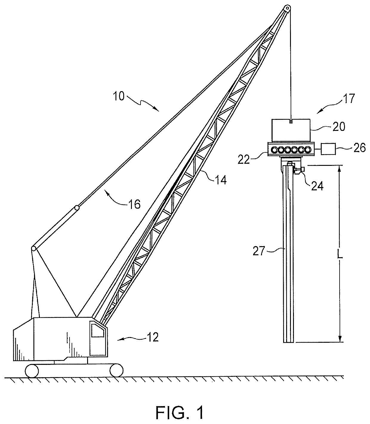
[0009]FIG. 1 is a schematic view of a conventional vibratory pile driver system, shown generally at 10. It includes a conventional construction crane 12, with an extending boom 14 and a system of control cables 16. At the end 18 of boom 14, the control cable extends downwardly to the vibratory pile driver assembly 17. The assembly generally includes a suppressor 20, a gearbox 22 and a clamp system 24, as well as a drive motor 26 for the assembly, usually hydraulic, although it could alternatively be an electric motor. All of these elements are conventional and hence do not require detailed explanation. The clamp 24 clamps the gearbox and the suppressor onto a pile 27 with a length L which in operation is to be driven into the ground.

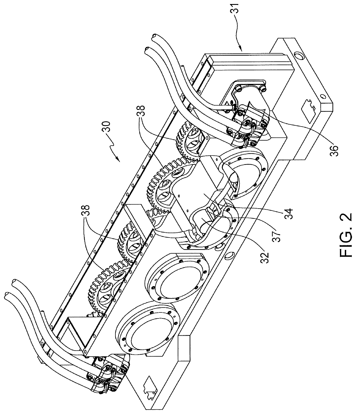
[0010]FIG. 2 shows a conventional vibratory pile driver gearbox. The gearbox shown generally at 30 includes a housing 31 generally made from steel. While the dimensions of the housing can vary, a typical system would be 14 inches by 96 inches by 24 inche...


PUM


Abstract

The lubrication system includes a hydraulic cylinder pump which receives oil from the pile driver gearbox and an actuating mechanism connected to the pump to move oil therein through an exit line to a spray mechanism in the gearbox housing, providing lubrication to the gearbox bearings before the gearbox elements begin to operate.

Description

TECHNICAL FIELD[0001]This invention relates generally to vibratory pile drivers, and more specifically to a lubrication arrangement for a gear box portion of a vibratory pile driver.BACKGROUND OF THE INVENTION[0002]It is vital in operation of a vibratory pile driver to properly lubricate the operating components of the gearbox portion of the pile driver, in particular the gearbox bearings, in order to reduce wear and extend their operating life. A splash-type lubrication system has historically been used, with a selected level of oil at the bottom of the gearbox. Typically, the oil level is generally enough to allow the eccentric and / or gear teeth to dip into the oil for lubrication. In operation of such a system, the counterweights and the gears will begin to turn when the motor, typically hydraulic, for the gearbox begins operation. However, at the very start of operation, the gearbox components, including the bearings, are dry. They are not lubricated by the conventional splash t...

Claims


Application Information

Patent Timeline
IPC IPC(8): E02D13/00E02D7/18F16N39/06F16N7/40
CPCE02D13/00E02D7/18F16N2210/12F16N7/40F16N39/06F16H57/0435F16H57/046F16H57/0471E02D29/02F16H57/0436F16N13/16
Inventor WHITE, JOHN L.
Owner WHITE JOHN L
Why Eureka
Try Eureka