Purification of oil-polluted water and device suitable therefor

a technology of oil-polluted water and purification device, which is applied in the direction of quarries, waste water treatment, and treatment water from quaries, etc., can solve the problems of not being able to discharge untreated into the environment, affecting the quality of oil, and wasting precious oil, etc., to achieve the effect of reducing the residual oil content of water, allowing long run times, and reducing the risk of contamination

Active Publication Date: 2019-07-23
EVIOLA
View PDF9 Cites 0 Cited by
  • Summary
  • Abstract
  • Description
  • Claims
  • Application Information

AI Technical Summary

Benefits of technology

[0012]The invention provides a device and a method with which the residual oil content of the water can be reduced considerably below currently feasible values, in order for example to enable further use of the deposit water for example as injection water or for generating process steam. The invention is intended to permit long run times with few interruptions for maintenance while simultaneously being possible to carry out at low cost. The intention is moreover also to provide an improved method for producing purified process water for extracting and / or refining petroleum as well as for extracting and / or refining petroleum.
[0014]The invention thus ensures that, during purification of the oil / water mixture, the membrane is coated with a film in the manner of a secondary membrane taking the form of the protective material. This is a film which is applied during operation which does not adhere permanently to the membrane but may instead be renewed or backflushed. The previous problem of the membrane being extremely rapidly clogged with free oil particles is avoided because the oil particles are kept away by the protective material.
[0019]The clarified water may then be taken from the ultrafiltration stage. Said clarified water now only comprises hydrocarbons which are dissolved in water. Solids or free or emulsified oil are completely separated. The clarified water is thus sufficiently pure to be used, for example, as injection water for injection wells in petroleum extraction without there being any risk of the pore spaces in the oil field becoming clogged. The clarified water taken from the ultrafiltration is furthermore also sterilized. This is of great significance to its suitability as injection water, since microorganisms decompose the petroleum stored in the oil field and could thus destroy the oil field. Even if it is not used as injection water, further processing, for example in an effluent treatment plant, is simplified by the greatly reduced residual oil content and can be carried out more inexpensively. After further treatment for desalting, for example by reverse osmosis, the clarified water may also be used for further purposes, such as for example as boiler feed water in petroleum processing.
[0021]Flow, by means of which the oil / water mixture is repeatedly passed by the membrane, may in particular be generated in the container. This further increases filter performance.
[0025]Iron(III) chloride, FeCl3, is preferably used as the additive. This additive reacts with the water of the mixture and gives rise to minuscule iron hydroxide particles [Fe(OH)3] as protective agent which rest on the membrane in the form of micro- or nanoparticles. Fe(OH)3 is insoluble in water and forms a very thin hydrophilic cover layer on the membrane which keeps the free oil and oil / water emulsion drops away from the membrane surface. The membrane thus cannot become clogged.
[0030]As mentioned, the protective material may preferably be removed by backflushing the membrane contrary to the direction of flow in which the water passes through the membrane in regular filter operation. This proceeds at intervals or when required. In this way, the membrane has the previous protective material removed from it and new protective material can be deposited.

Problems solved by technology

Oil / water mixtures are very harmful to the environment and therefore cannot be discharged untreated into the environment, for example requiring elaborate disposal arrangements.
On the one hand, this involves a considerable waste of precious oil and, on the other hand, the water cannot be discharged into the environment due to the considerable contamination with oil but must instead be further treated and purified.
Currently available treatment methods and devices, however, have considerable disadvantages with regard to costs and treatment performance.
Disposal of the water is extremely problematic at such a high loading.
Sometimes the water is transferred into special wastewater lagoons which involves considerable environmental pollution.
While this practice does indeed initially get rid of the water, it makes groundwater deposits useless for future extraction of drinking water.
However, even this loading is still too high for direct discharge of the water, such that here too the water can only be discharged to an effluent treatment plant, so causing considerable additional costs.
A solution which is at first glance obvious in petroleum extraction of using the contaminated deposit water as injection water for the injection wells is in many cases likewise not possible due to the residual oil content of the water.
If injected into the oil field, the oil particles can clog the pores in the oil-bearing formation and so considerably reduce output from the oil field and, in extreme cases, may bring extraction to a virtual standstill.
Even if it is possible to force the deposit water back into the oil field, there are further related problems.
Such precise input is, however, almost impossible to ensure reliably.
There is therefore always a risk that the introduced deposit water will not remain in the oil field, but will instead be forced into other rock strata where it may cause contamination, in extreme cases in the aquifer too.
However, such investigations revealed the problem that the membranes used are likewise irreversibly clogged by the oil particles within a short time.
While using ceramic membranes has made backflushing feasible, such that the membranes can be used over an extended period, the service period of these special ceramic membranes between flushing operations is very short and the membrane costs are very high.

Method used


Image

  • Purification of oil-polluted water and device suitable therefor
  • Purification of oil-polluted water and device suitable therefor
  • Purification of oil-polluted water and device suitable therefor

Examples


Embodiment Construction

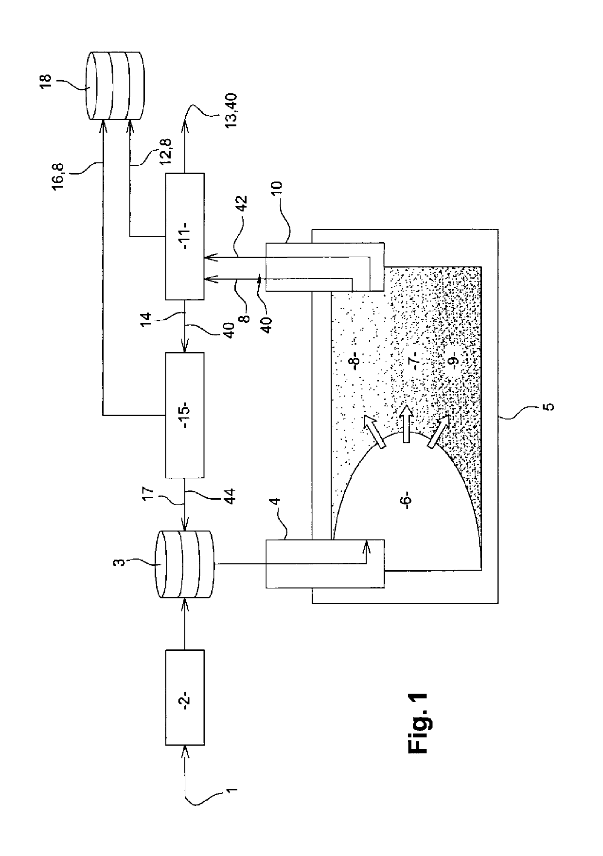
[0045]FIG. 1 shows an external water source 1 (for example either an underground aquifer or seawater) from which water may be taken as injection water and, after treatment in a treatment plant 2 (for example seawater desalination), pumped via an injection well 4 into an oil field 5. In order to compensate fluctuations, the injection water may previously be held in intermediate storage in a tank 3. The introduced injection water results in the formation in the oil field 5 of a water bank 6 which presses an oil bank 7 towards an extraction well 10. The oil bank 7 is here composed of a proportion of oil 8, in this case petroleum, and a proportion of formation water 9. Due to its density, the oil 8 is located more in the higher part of the oil bank 7, while the formation water 9 is mainly stored in the lower zones thereof.

[0046]A mixture 40 of oil 8 and water 42 (process water, in this case formation water 9 and / or injection water) now emerges from the extraction well 10. Said mixture i...


PUM

PropertyMeasurementUnit
concentrationaaaaaaaaaa
sizeaaaaaaaaaa

Abstract

In a method for purifying an oil (8) / water (42) mixture (40), the mixture (40) is fed to a container (48) having an ultrafiltration unit (52) with a membrane (30), and a protective material (50) is added to the mixture (40), which protective material, directly or after chemical reaction with the water from the mixture (40), as a film (62) on the membrane (30), keeps free oil (8) away from said membrane. Purified process water for extracting and / or refining of petroleum (8) is thus produced from process water (42) which is contaminated with petroleum (8). A purification device (64) substantially comprises a container (48) having an ultrafiltration unit (52) with a membrane (30), a feed line (28) to the container (48) and an addition device (27) for protective material (50) in the flow path (56) to the membrane (30).

Description

TECHNICAL FIELD[0001]The invention relates to a method and a device for purifying a mixture of water contaminated with oil, and to a method for producing purified process water during the extraction and / or refining of petroleum.BACKGROUND[0002]Extracting petroleum essentially involves extracting a petroleum / water mixture from the ground. In newly developed oil fields, this mixture consists of the formation water already present in the oil-bearing stratum and the oil which is to be extracted. In older oil fields, extraction of the petroleum / water mixture involves forcing water into the petroleum formation through injection wells which are located at a certain distance from the extraction well. Under the pressure developed in this manner, the water flows in the oil-bearing stratum to the extraction well and, in so doing, carries petroleum with it which may then be taken from the extraction well together with the injection water and any formation water which is present.[0003]This petro...

Claims


Application Information

Patent Timeline
Patent Type & Authority Patents(United States)
IPC IPC(8): B01D61/16C10G31/08B01D65/08C02F1/44C02F1/52E21B43/20E21B43/40C02F101/32C02F103/10C02F103/36
CPCC02F1/444B01D65/08C02F1/5245C10G31/08E21B43/20E21B43/40B01D61/16C10G2300/805B01D2321/04B01D2321/16B01D2321/2091C02F1/52C02F2101/32C02F2103/10C02F2103/365C02F2303/16C10G2300/1033C10G2300/202B01D65/04E21B43/35
Inventor BAEUERLE, ULRICH
Owner EVIOLA
Why Eureka
Try Eureka