Integrated electro-optic frequency comb generator

Active Publication Date: 2021-03-11
HYPERLIGHT CORP
View PDF0 Cites 3 Cited by
  • Summary
  • Abstract
  • Description
  • Claims
  • Application Information

AI Technical Summary

Problems solved by technology

However, the drawbacks of this method include narrow comb width, high microwave driving power requirement due to multiple phase shifters and amplifiers, complex microwave components for tuning microwave phases and high

Method used


Image

  • Integrated electro-optic frequency comb generator
  • Integrated electro-optic frequency comb generator
  • Integrated electro-optic frequency comb generator

Examples


Embodiment Construction

[0029]While the present teachings are described in conjunction with various embodiments and examples, it is not intended that the present teachings be limited to such embodiments. On the contrary, the present teachings encompass various alternatives and equivalents, as will be appreciated by those of skill in the art.

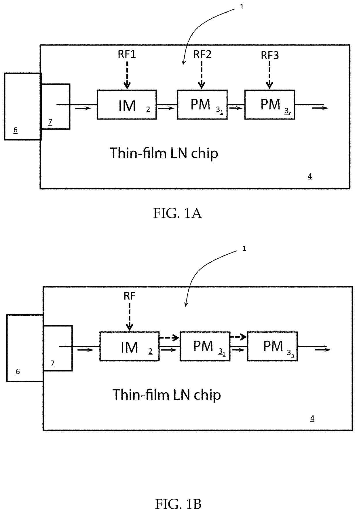
[0030]An integrated electro-optic frequency comb generator may include an ultralow loss integrated thin-film lithium niobate or lithium tantalate platform, which may be fabricated in accordance with the methods disclosed in WO 2018 / 031916 filed Aug. 11, 2017 by Wang et al., which is incorporated herein by reference. The platform enables low power consumption comb generation spanning over a wider range of optical frequencies. The compact integrated electro-optic modulator based frequency comb generator, provides the benefits of an integrated lithium niobate or lithium tantalate platform including low waveguide loss, high electro-optic modulation efficiency, small bending...


PUM


Abstract

An integrated electro-optic frequency comb generator based on ultralow loss integrated, e.g. thin-film lithium niobate, platform, which enables low power consumption comb generation spanning over a wider range of optical frequencies. The comb generator includes an intensity modulator, and at least one phase modulator, which provides a powerful technique to generate a broad high power comb, without using an optical resonator. A compact integrated electro-optic modulator based frequency comb generator, provides the benefits of integrated, e.g. lithium niobate, platform including low waveguide loss, high electro-optic modulation efficiency, small bending radius and flexible microwave design.

Description

CROSS-REFERENCE TO RELATED APPLICATIONS[0001]This application claims priority to U.S. Provisional Application No. 62 / 898,051, filed Sep. 10, 2019, which is hereby incorporated by reference in its entirety.TECHNICAL FIELD[0002]The present invention relates to optical devices and electro-optic frequency comb generators, and in particular to an integrated electro-optic frequency comb generator.BACKGROUND[0003]An electro-optic modulator (EOM) is an optical device in which an electro-optic element is used to modulate a beam of light using an electrical, e.g. voltage, signal. The modulation may be imposed on the phase, frequency, amplitude, or polarization of the beam. Modulation bandwidths extending into the gigahertz range are possible with the use of high bandwidth modulators. The electro-optic effect is the change in the refractive index of the E / O material in the electro-optic element resulting from the application of a DC or alternating electric field. The refractive index change is...

Claims


Application Information

Patent Timeline
IPC IPC(8): G02F1/355G02F1/365
CPCG02F1/3551G02F2203/56G02F1/365G02F2201/16G02F1/225G02F1/035G02F2/02
Inventor ZHANG, MIANREIMER, CHRISTIANLUKE, KEVIN
Owner HYPERLIGHT CORP
Why Eureka
Try Eureka