
Receiver

a receiver and receiver technology, applied in the field of receivers, can solve the problems of reducing the number of frequencies to be monitored, too slow frequency scanning to meet the requirements of some applications, etc., and achieve the effects of reducing or avoiding reducing the delay of retuning, and increasing the speed

Active Publication Date: 2021-03-11
KIRINTEC LTD
View PDF5 Cites 3 Cited by
  • Summary
  • Abstract
  • Description
  • Claims
  • Application Information

AI Technical Summary

Benefits of technology

The patent describes a way to quickly scan a range of frequencies without likelihood of delays during retuning of oscillators. This is achieved by using two oscillators, with the first one used to determine if transmissions are being done, and the second one used for monitoring and retuning. The use of additional oscillators can further improve the speed of scanning.

Problems solved by technology

Whilst a receiver device of the type outlined hereinbefore may operate satisfactorily in a number of applications, the time taken in retuning the oscillator before a subsequent frequency can be monitored results in the scanning of a range of frequencies being too slow to meet the requirements of some applications, or may require a reduced number of frequencies to be monitored.

Method used


Image

  • Receiver
  • Receiver

Examples


Embodiment Construction

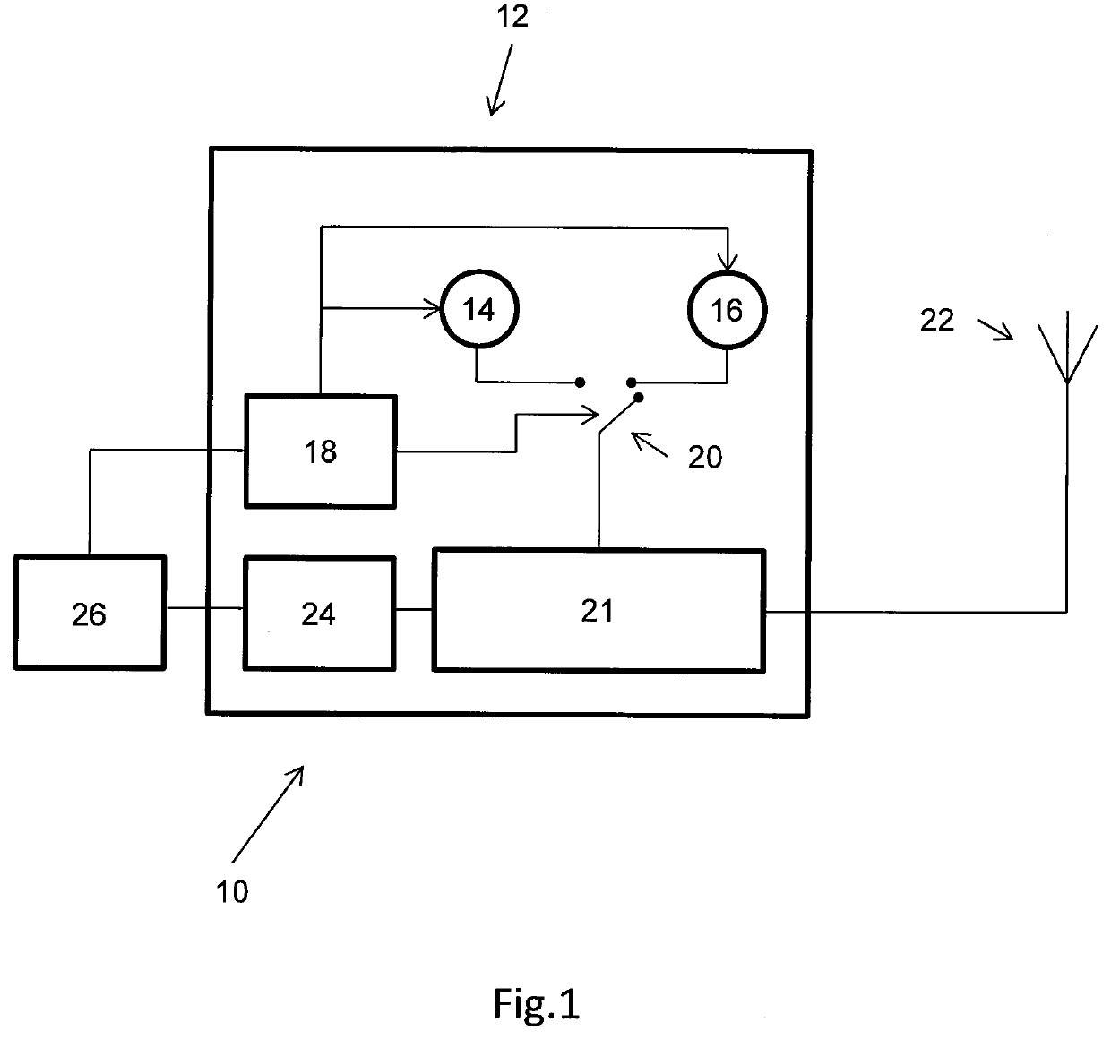
[0031]Referring to the accompanying drawing, a receiver 10 is illustrated intended for use in monitoring a range of radio transmission frequencies in order to identify which of the frequencies is in use at any given time. The receiver 10 comprises a unit 12 including a first tuneable oscillator 14 and a second tuneable oscillator 16. The unit 12 further comprises a controller 18 operable to tune the first and second tuneable oscillators 14, 16 to control the frequencies to which they are tuned at any given time. The controller 18 controls the operation of the oscillators 14, 16 such that the oscillators are tuned to respective frequencies.

[0032]The oscillators 14, 16 are connected to a switch device 20 which controls which of the oscillators 14, 16 is connected to a receiver circuit 21 to which an antenna 22 is connected, at any given time. The switch device 20 is controlled by the controller 18.

[0033]The switch device 20 may be any element capable of selecting one of the first and ...


PUM


Abstract

A receiver and associated methods are described. The receiver comprises a first oscillator 14, a second oscillator 16, a controller 18 operable to control frequencies to which the first and second oscillators are tuned, and a discrimination circuit 24 operable to receive and monitor transmitted signals; wherein the discrimination circuit is configured to receive a signal at a first transmission frequency determined based on a first tuned frequency to which the first oscillator is tuned, and to determine, in a capture time period, whether data is being transmitted at the first transmission frequency; wherein the controller is configured to tune, in a tuning time period, the second oscillator to a second tuned frequency; and wherein the tuning time period is shorter than the capture time period.

Description

FIELD OF THE INVENTION[0001]This invention relates to a receiver, and in particular to a receiver suitable for determining whether a signal has been transmitted on one or more of a range of radio transmission frequencies.BACKGROUND OF THE INVENTION[0002]There are a number of applications in which it is desired to be able to scan a range of radio transmission frequencies to identify those that are in use (e.g. are being used to transmit signals comprising information) at any given period of time. One receiver device suitable for use in such an application includes an oscillator tuned to a selected frequency controlled by a controller, the oscillator being connected to a suitable antenna. Radio transmissions received by the antenna and transmitted at the frequency to which the oscillator is tuned can thus be received, and hence a discrimination circuit of the receiver device can be used to ascertain whether or not that frequency is in use. By periodically adjusting the frequency to wh...

Claims


Application Information

Patent Timeline
Patent Type & Authority Applications(United States)
IPC IPC(8): H03J7/18H04B1/18H04B1/00H03B5/06
CPCH03J7/18H04B1/18H04H2201/60H03B5/06H04H2201/13H04B1/0007H04B1/06
Inventor HILL, PAULPOMEROY, LEE MICHAELHARRISON, RICHARD
Owner KIRINTEC LTD
Learn More