Manufacturing apparatus and manufacturing method for hat-shaped section component with curved projection portion

a technology of hat-shaped section and manufacturing method, which is applied in the direction of metal-working apparatus, manufacturing tools, stripping devices, etc., can solve the problems of reducing productivity, forming cracks in the top plate, and increasing the thickness of the pad, so as to reduce the probability of cracking, and reduce the effect of productivity

Pending Publication Date: 2021-03-18
TOYOTA JIDOSHA KK
View PDF4 Cites 0 Cited by
  • Summary
  • Abstract
  • Description
  • Claims
  • Application Information

AI Technical Summary

Benefits of technology

[0024]Restraint force (pad restraint force) by the pad for restraining a crack from being formed in the top plate in the course of stretch-flanging increases in proportion to the material strength and the plate thickness of the workpiece. In terms of this, the manufacturing apparatus and the manufacturing method of the present disclosure each of which can restrain a decrease in productivity and occurrence of a crack in the top plate by partially applying the pad restraint force can be preferably applied to a workpiece made of high tensile steel.
[0025]As described above, with the manufacturing apparatus and the manufacturing method, according to the present disclosure, each for a hat-shaped section component including a curved projection portion, it is possible to restrain a decrease in productivity and occurrence of a crack in a top plate.

Problems solved by technology

That is, in a case where a hat-shaped section component including a curved projection portion curved in its longitudinal direction is manufactured, if a to-become-top-plate portion is not pressed by a pad so as to prevent occurrence of longitudinal displacement (slip) in a workpiece, the to-become-top-plate portion is displaced in the longitudinal direction in the course of stretch-flanging (molding of a vertical wall between a top plate and a flange), thereby resulting in that a crack is formed in the top plate.
However, when the thickness of the pad is relatively increased, the following problem occurs.
This causes such a problem that the productivity decreases.

Method used


Image

  • Manufacturing apparatus and manufacturing method for hat-shaped section component with curved projection portion
  • Manufacturing apparatus and manufacturing method for hat-shaped section component with curved projection portion
  • Manufacturing apparatus and manufacturing method for hat-shaped section component with curved projection portion

Examples


Embodiment Construction

[0045]With reference to the drawings, the following describes an embodiment to carry out the present disclosure.

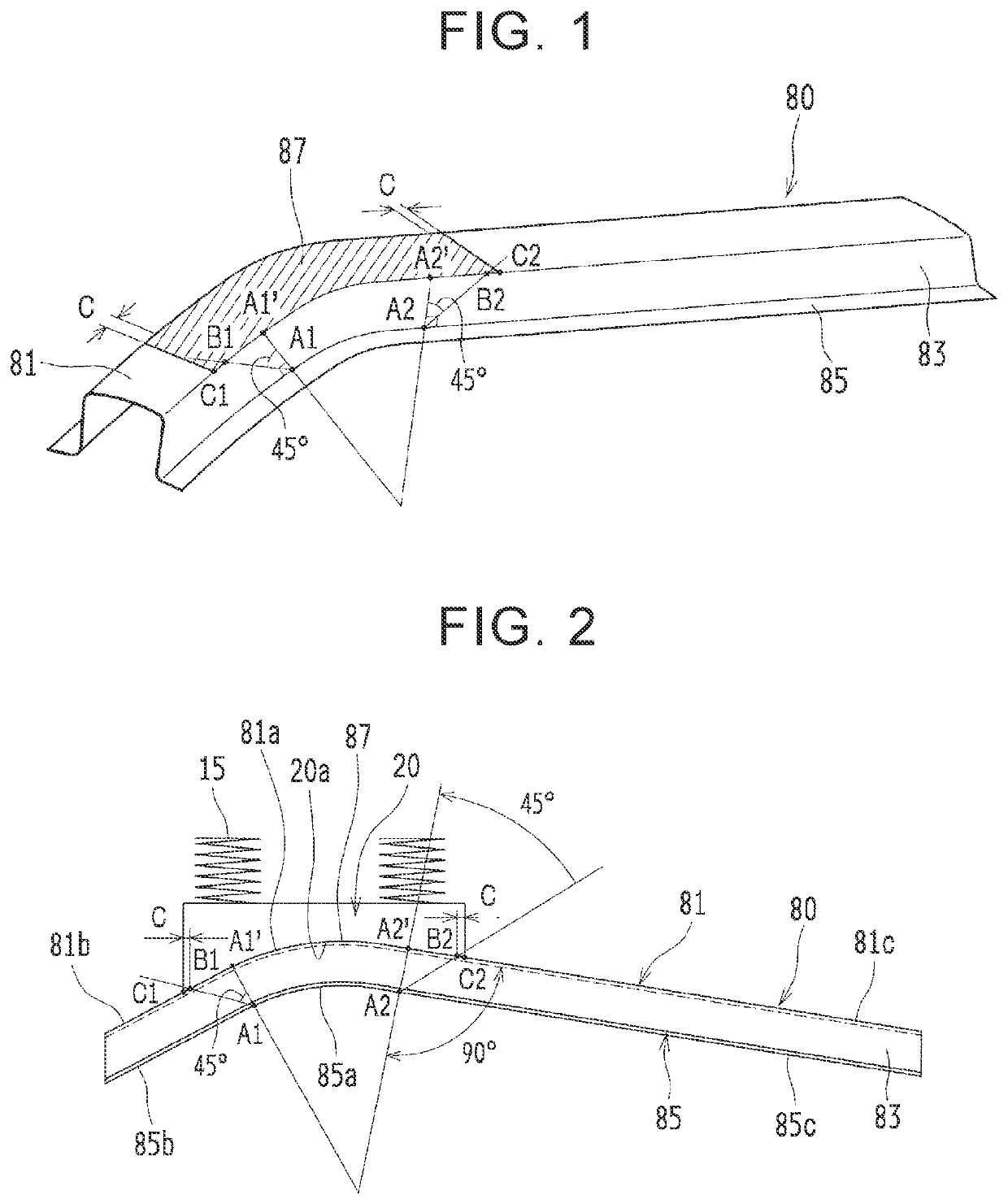
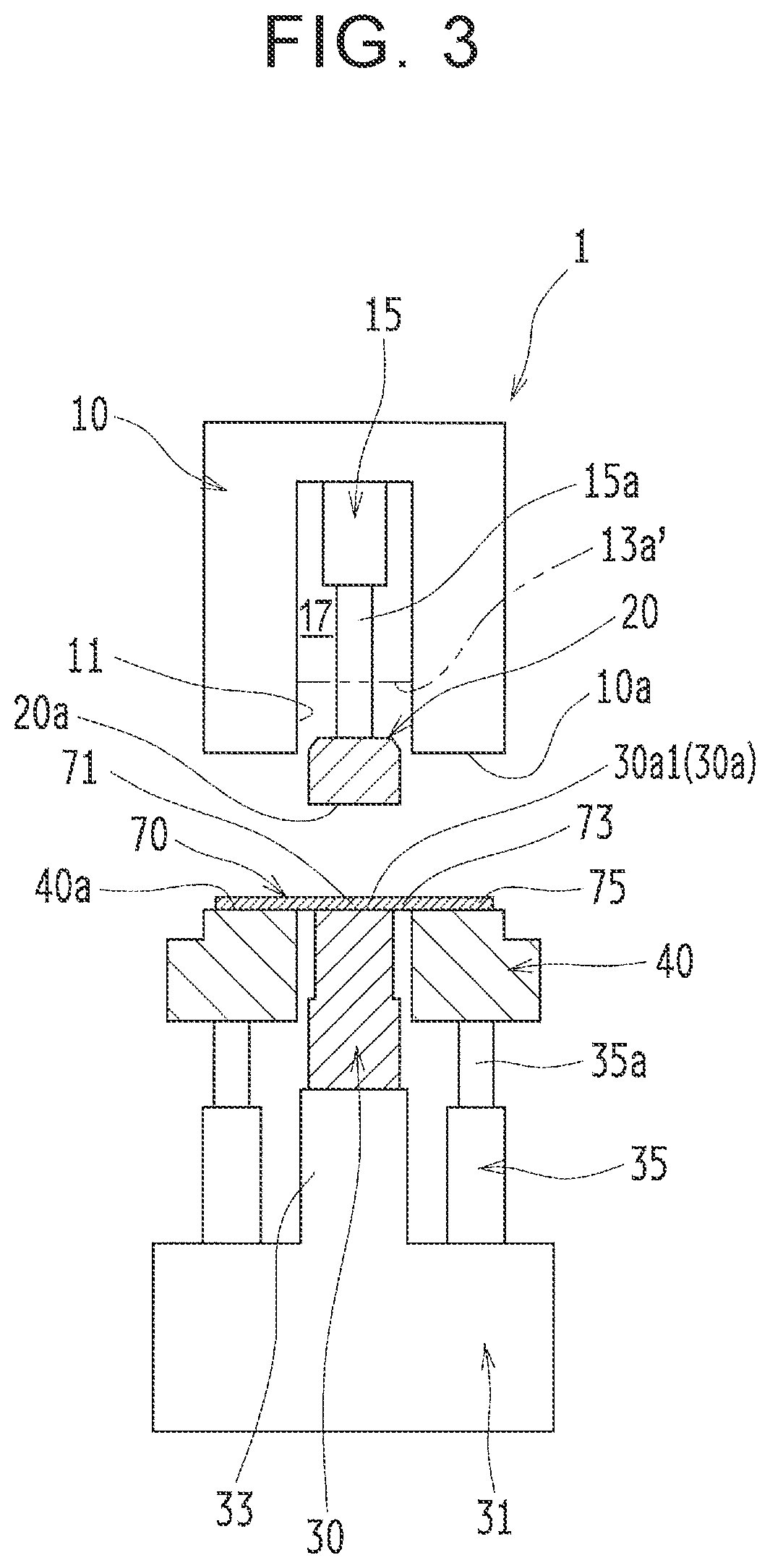
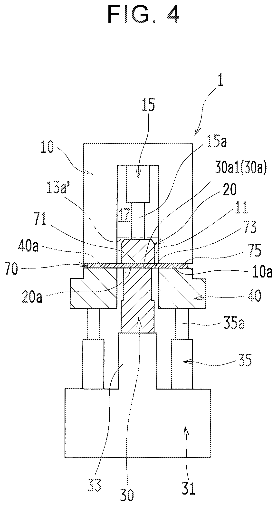
[0046]FIG. 1 is a perspective view schematically illustrating a hat-shaped section component 80 manufactured by a manufacturing apparatus 1 and a manufacturing method according to the present embodiment, and FIG. 2 is a side view schematically illustrating a relationship between the hat-shaped section component 80 and a pad 20. The hat-shaped section component 80 is manufactured by performing press working (drawing), by use of the manufacturing apparatus 1 (described below), on a flat-shaped workpiece 70 (see FIG. 2) made of high tensile steel (a high tensile material) having a tensile strength equal to or more than 490 MPa (preferably equal to or more than 980 MPa), for example.

[0047]As illustrated in FIG. 1, the hat-shaped section component 80 includes: a top plate 81 including a curved projection portion 87 curved in the longitudinal direction so as to project upward; a...


PUM

PropertyMeasurementUnit
tensile strengthaaaaaaaaaa
pressing forceaaaaaaaaaa

Abstract

Provided is a manufacturing apparatus for manufacturing a hat-shaped section component including a curved projection portion such that a to-become-top-plate portion is pressed by a punch in a state where a to-become-flange portion is sandwiched between a die and a holder. The manufacturing apparatus includes the punch having a first mold surface including a curved projection portion mold surface, the holder, and the die having a fourth mold surface facing the first mold surface. An opening is formed in a part, of the fourth mold surface, that corresponds to the curved projection portion mold surface. The manufacturing apparatus includes a pad provided in the die and having a fifth mold surface facing the curved projection portion mold surface, the pad being configured to be relatively movable upward against downward biasing force so that the fifth mold surface becomes flush with the fourth mold surface.

Description

INCORPORATION BY REFERENCE[0001]The disclosure of Japanese Patent Application No. 2019-166922 filed on Sep. 13, 2019 including the specification, drawings and abstract is incorporated herein by reference in its entirety.BACKGROUND1. Technical Field[0002]The present disclosure relates to a manufacturing apparatus and a manufacturing method each for a component having a hat-shaped section (hereinafter also referred to as a “hat-shaped section component”) with a curved projection portion curved in a longitudinal direction.2. Description of Related Art[0003]In a case where a hat-shaped section component used for a vehicle frame member and so on is manufactured, press working (drawing) is often performed on a metal flat-shaped workpiece by use of a manufacturing apparatus such that the workpiece has a hat-shaped section, the manufacturing apparatus including a die, a punch, a holder, and so on as a metal mold.[0004]More specifically, in a case where a hat-shaped section component is manu...

Claims


Application Information

Patent Timeline
Patent Type & Authority Applications(United States)
IPC IPC(8): B21D22/02
CPCB21D22/025B21D22/26B21D24/00B21D24/06B21D24/08B21D45/08B21D24/04B21D5/06B21D22/22
Inventor NOJIRI, ISAO
Owner TOYOTA JIDOSHA KK
Why Eureka
Try Eureka