Railway condition monitoring device, railway vehicle bogie, railway vehicle, railway brake control device

a technology for condition monitoring and railway vehicles, which is applied in the direction of railway signalling, railway signalling and safety, and vehicle signalling, etc. it can solve the problems of surplus maintenance man-hours and replacement materials, affecting the operation of railway vehicles, and disadvantageous in terms of cost, so as to improve versatility

Pending Publication Date: 2021-03-18
NABLESCO CORP
View PDF8 Cites 3 Cited by
  • Summary
  • Abstract
  • Description
  • Claims
  • Application Information

AI Technical Summary

Benefits of technology

[0007]The present invention has been made in view of these problems, and an object of the present invention is to provide a condition monitoring device for a railway capable of improving versatility.

Problems solved by technology

When the rails, the wheels, and the like of the railways are worn out and fail, there is a risk of affecting an operation of the railway vehicle.
In this case, maintenance man-hours and replacement materials are surplus, which is disadvantageous in terms of cost.
On the other hand, if the maintenance intervals are long, there is a high possibility of failure when the rails, the wheels, and the like are worn out faster than expected.

Method used


Image

  • Railway condition monitoring device, railway vehicle bogie, railway vehicle, railway brake control device
  • Railway condition monitoring device, railway vehicle bogie, railway vehicle, railway brake control device
  • Railway condition monitoring device, railway vehicle bogie, railway vehicle, railway brake control device

Examples


first embodiment

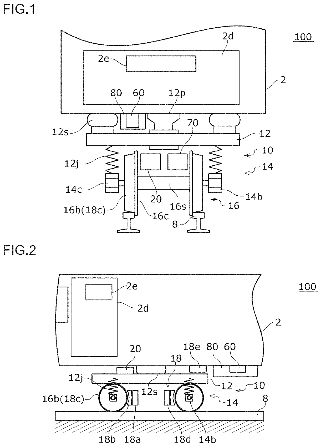
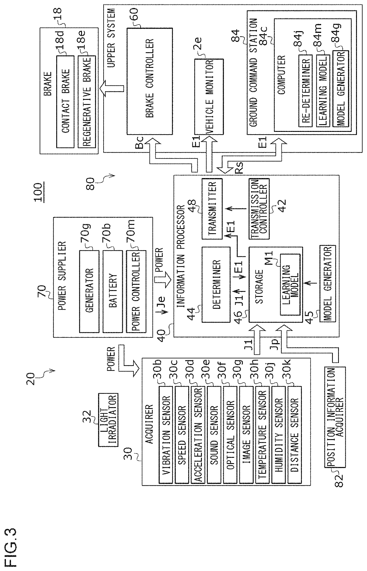
[0047]A railway condition monitoring device 20 (hereinafter, simply referred to as “condition monitoring device 20”) and a railway brake control device 80 (hereinafter, simply referred to as “brake control device 80”) according to a first embodiment of the present invention will be described with reference to FIGS. 1 to 5. FIG. 1 is a schematic diagram of a front view illustrating a railway vehicle 100. FIG. 2 is a schematic diagram illustrating the railway vehicle 100 as viewed from the side. FIG. 3 is a block diagram schematically illustrating a condition monitoring device 20 and a brake control device 80 according to the present embodiment. The condition monitoring device 20 and the brake control device 80 according to the present embodiment are mounted on the railway vehicle 100. In particular, the condition monitoring device 20 is mounted on the bogie 10 of the railway vehicle 100.

[0048]Each functional block illustrated in each drawing of the present disclosure including FIG. 3...

second embodiment

[0103]A railway condition monitoring device 20 and a railway brake control device 80 according to a second embodiment of the present invention will be described with reference to FIGS. 1, 2, and 6 to 8. The condition monitoring device 20 and the brake control device 80 according to the present embodiment are mounted on the railway vehicle 100. FIG. 6 is a block diagram schematically illustrating a condition monitoring device 20 and a brake control device 80 according to the present embodiment.

[0104]As illustrated in FIG. 6, the condition monitoring device 20 includes an acquirer 30, an information processor 40, a power supplier 70, and a position information acquirer 82. In addition, the brake control device 80 includes the acquirer 30, the information processor 40, and a brake controller 60. The information processor 40 includes a determiner 44, a storage 46, a transmitter 48, and a transmission controller 42. The acquirer 30 includes a vibration sensor 30b and a speed sensor 30c. ...

third embodiment

[0139]A railway condition monitoring device 20 and a railway brake control device 80 according to a third embodiment of the present invention will be described with reference to FIGS. 1, 2, and 9 to 12. The condition monitoring device 20 and the brake control device 80 according to the present embodiment are mounted on the railway vehicle 100. FIG. 9 is a block diagram schematically illustrating a condition monitoring device 20 and a brake control device 80 according to the present embodiment.

[0140]Brake squeal may occur when the contact brake 18d is operated. The brake squeal is an abnormal noise in which vibration from a friction surface caused by a touch of a brake shoe 18b to a braking member 18c during braking is amplified and generated by the brake shoe 18b or the braking member 18c, and is called braking noise. The brake squeal occurs due to the wear or the like of the friction surface of the brake shoe 18b and the braking member 18c. If the brake squeal occurs, the brake sho...


PUM


Abstract

A railway condition monitoring device includes an acquirer structured to be attached to a railway vehicle bogie and acquire state information on one or more state of vibration, speed, acceleration, sound, reflected light, image, temperature, humidity, and a wheel diameter, a determiner structured to be attached to a bogie, perform a determination of a state of a track on which the bogie travels or a state of the bogie based on the state information acquired by the acquirer, and provide the determination result, a transmitter structured to be attached to the bogie and transmit the determination result to an outside of the bogie, and a power supplier structured to be attached to the bogie and supply power to the acquirer and the transmitter.

Description

CROSS REFERENCE TO RELATED APPLICATIONS[0001]The present invention claims priority under 35 U.S.C. § 119 to Japanese Patent Application No. 2019-167060, filed on Sep. 13, 2019 and claims priority under 35 U.S.C. § 119 to Japanese Patent Application No. 2020-135303, filed Aug. 7, 2020, the entire content of which is incorporated herein by reference.BACKGROUND OF THE INVENTIONField of the Invention[0002]The present invention relates to a railway condition monitoring device, a railway vehicle bogie, a railway vehicle, and a railway brake control device.Description of the Related Art[0003]A detection device that detects flat wear and the like of wheels has been known (for example, JP S60-000311 A). The detection device described in JP S60-000311 A includes a wheel detector and a shock vibration detection element which are installed at a certain distance along a longitudinal direction of a rail, and a processor that processes output signals of the wheel detector and the shock vibration d...

Claims


Application Information

Patent Timeline
Patent Type & Authority Applications(United States)
IPC IPC(8): B61L3/00
CPCB61L3/002B61L15/0081B61L23/042B61L15/0027
Inventor MORITA, MITSUMASASAKURAI, KYOKOKATO, HIDEOOMACHI, RONPEIKASAMATSU, MASAKIKIGAMI, SHOGONAKAMURA, KAZUHITOWADA, TAKASHI
Owner NABLESCO CORP
Why Eureka
Try Eureka