Image forming apparatus

a technology of image forming apparatus and surface potential, which is applied in the direction of electrographic process apparatus, corona discharge, instruments, etc., can solve the problems of low detection accuracy, fluctuation of inability to stabilize the surface potential of photosensitive drum during exposur

Inactive Publication Date: 2021-03-18
CANON KK
View PDF0 Cites 0 Cited by
  • Summary
  • Abstract
  • Description
  • Claims
  • Application Information

AI Technical Summary

Benefits of technology

[0024]The present invention succeeds in providing a technique for precisely correcting the surface potential of a photosensitive drum, even upon replacement of a process cartridge in an image forming apparatus.

Problems solved by technology

However, the surface potential of the photosensitive drum fluctuates under the influence of variability in a high-voltage power source of the image forming apparatus main body and variability in the process cartridge.
The surface potential of the photosensitive drum during exposure may be not stable, depending on the usage situation of the process cartridge inserted in the main body, and detection accuracy may be low.

Method used


Image

  • Image forming apparatus
  • Image forming apparatus
  • Image forming apparatus

Examples


embodiment 1

Explanation of an Image Forming Apparatus

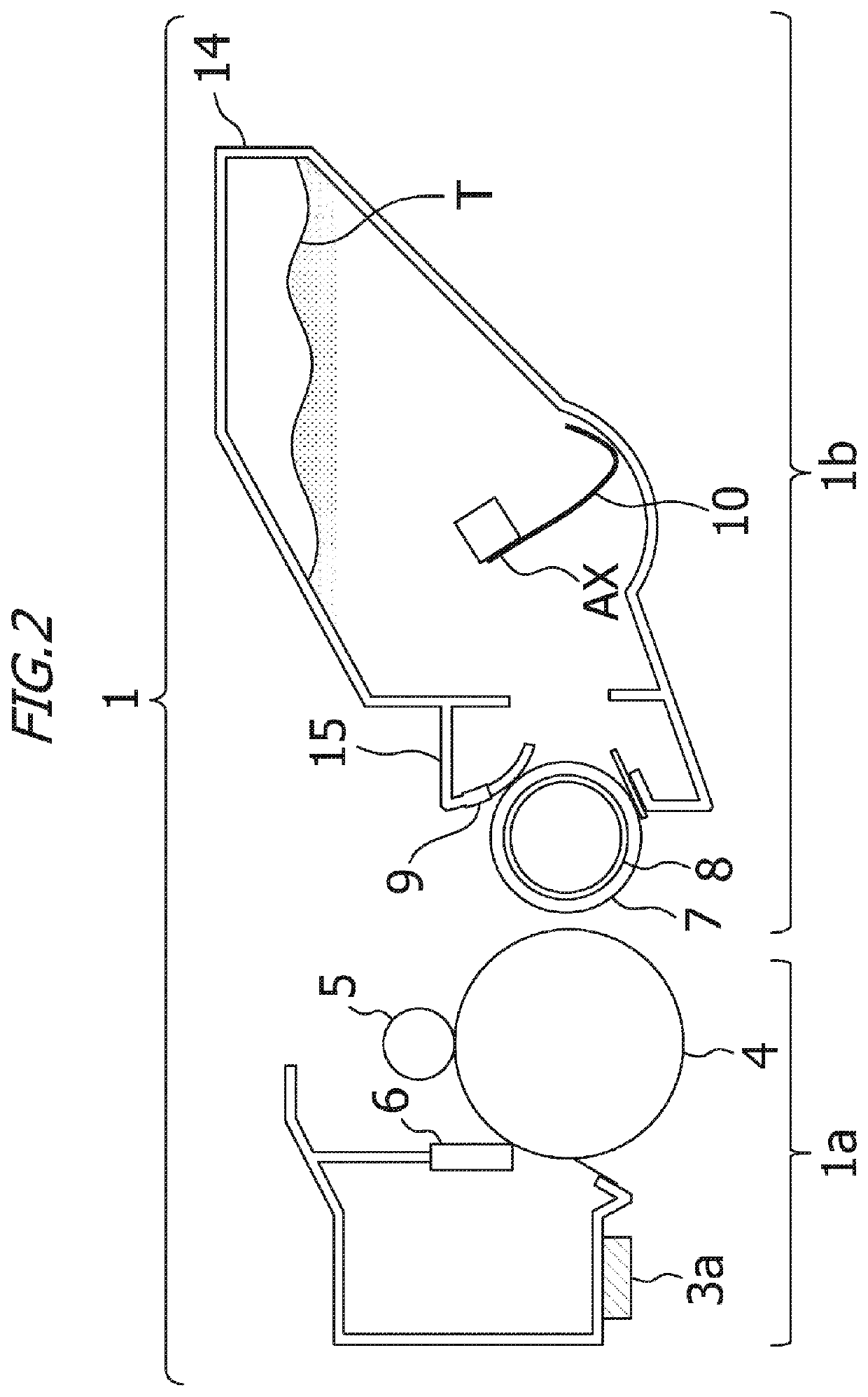
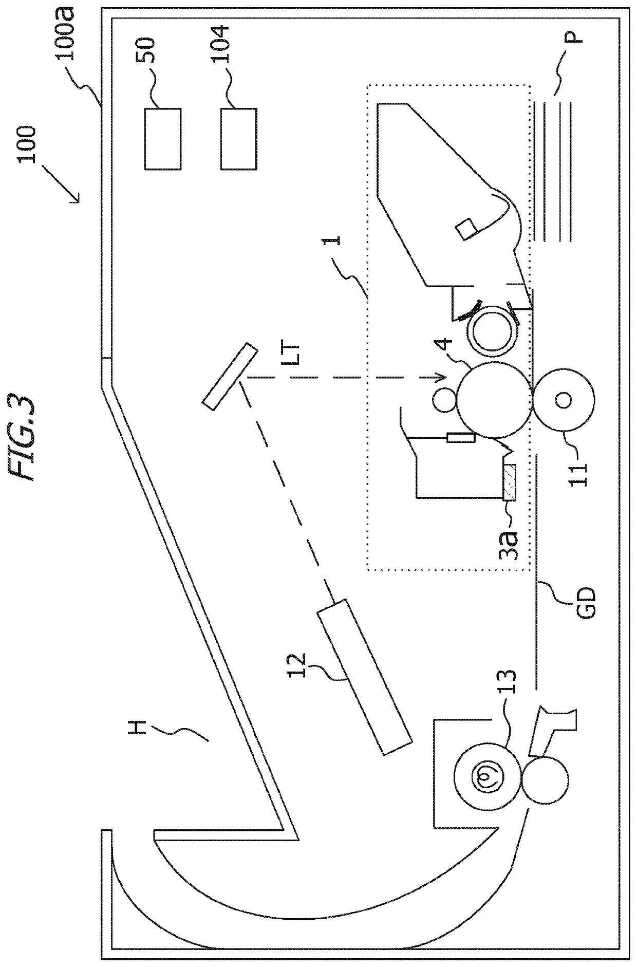
[0034]The overall structure of an electrophotographic image forming apparatus 100 will be explained with reference to the schematic cross-sectional diagram of FIG. 3. The image forming apparatus 100 has an image forming apparatus main body 100a and a process cartridge 1. The image forming apparatus 100 of FIG. 3 is in a state having the process cartridge 1 attached thereto. Schematically, the image forming apparatus main body 100a is provided with an exposure device 12, a transfer roller 11, a fixing apparatus 13, a control unit 50 and a high-voltage power source 104. The process cartridge 1 is replaceable relative to the image forming apparatus main body 100a, for the purpose of replacement or maintenance.

[0035]An outline of an image forming operation will be explained next. A control unit 50 (control portion) acquires image information of an image to be formed, through external reception or through reading from a memory. The control unit 50...

embodiment 2

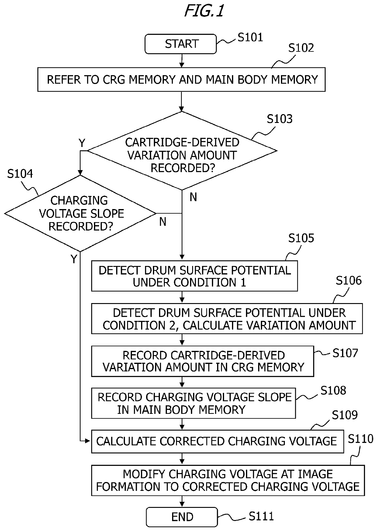
[0123]Embodiment 2 of the present invention will be explained next. In Embodiment 2, the detection content of the surface potential in the maintenance mode is determined on the basis of the information recorded in the CRG memory 3a and the main body memory 3b, to thereby reduce detection time and to shorten downtime. A description of features of constituent elements and processes that overlap with those of Embodiment 1 will be omitted herein.

[0124]There are two detection modes (detection conditions) in Embodiment 1.

[0125]Specifically, surface potential is not detected in a case where both data of the charging voltage slope α and the charging voltage variation amount β are stored, whereas detection is performed under both a first and a second condition in a case where either one of the slope α and the variation amount β is not stored. In Embodiment 2, by contrast, there are three detection modes. Specifically, detection is not performed in a case where both the slope α and the variat...


PUM


Abstract

An image forming apparatus, including: a potential detection portion that detects information relating to a surface potential formed on a surface of an image bearing member; and a control portion that calculates a first charging voltage, at which the surface potential has a first value, on the basis of the information, and that controls the potential detection portion, wherein the potential detection portion acquires a plurality of the information items under a plurality of conditions where charging voltage differs, and wherein the control portion calculates the first charging voltage from a deviation of the charging voltage, which is a deviation deriving from an apparatus main body and calculated on the basis of the plurality of the information items and the first value, and controls a power supply portion so that the first charging voltage is applied to a charging member during an image forming operation.

Description

BACKGROUND OF THE INVENTIONField of the Invention[0001]The present invention relates to an image forming apparatus.Description of the Related Art[0002]Image forming apparatuses known in the prior art include, for instance, copying machines relying on electrophotographic systems or electrostatic recording systems, laser beam printers, facsimile machines and the like. Using a process cartridge in such image forming apparatuses for the purpose of facilitating maintenance is a known feature. The process cartridge is herein a member, in which a photosensitive drum, a charging roller, a cleaning member, a developing sleeve, a toner container and so forth are integrated together, and which is configured to be attachable / detachable to / from the image forming apparatus.[0003]During image formation using the process cartridge, the surface of the photosensitive drum is uniformly charged by discharge of the charging roller. The potential at this time is referred to as dark area potential VD. Sub...

Claims


Application Information

Patent Timeline
Patent Type & Authority Applications(United States)
IPC IPC(8): G03G15/02
CPCG03G15/0275
Inventor FUKUSHIMA, NAOKI
Owner CANON KK
Why Eureka
Try Eureka