Touch and stylus sensing

a technology of stylus and sensing device, applied in the field of touch and stylus sensing device, can solve the problems of affecting the effect of eddy current loss, so as to achieve sufficient signal-to-noise ratio, increase the amount of effort, and cost-effective

Inactive Publication Date: 2021-03-18
AZOTEQ HLDG LTD
View PDF0 Cites 0 Cited by
  • Summary
  • Abstract
  • Description
  • Claims
  • Application Information

AI Technical Summary

Benefits of technology

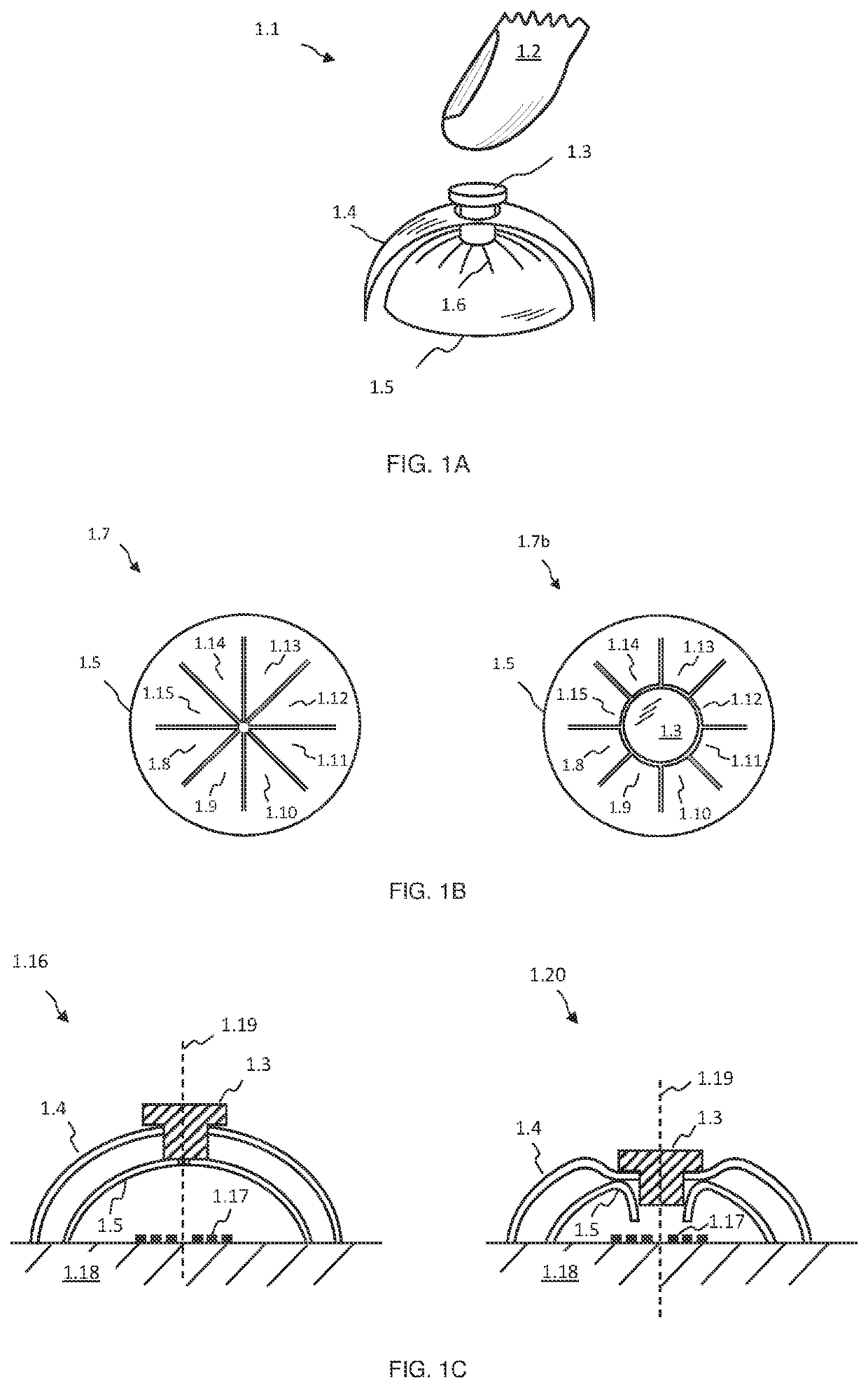
[0007]In a first embodiment of the present invention, a push button structure may be realized as follows. A conductive dome structure may be located over a coil structure. The conductive dome structure may have a number of slits cut into its apex. When the apex is pressed downwards, an opening in the dome structure is formed due to said slits. A magnetic member, for example a ferrite member, may be located above the dome structure, and aligned with the centre of said apex. Said magnetic member may be resiliently supported and held in place by a flexible member. When a user applies less than a specific amount of force to the magnetic member or to the flexible member in a downwards direction, said magnetic member may move slightly and apply a finite amount of pressure on said dome apex. However, if a user applies more than a specific amount of force to said magnetic or flexible members, the flexible member may suddenly deflect downwards, also known as snapping through. This may result in the magnetic member pressing with sufficient force on said apex and slits to cause an opening to form in the dome apex, wherein said magnetic member may protrude through said opening. In other words, when said flexible member snaps through, the magnetic member may suddenly move through the opening in said dome apex, and may come close to said coil structure. Therefore, the snap through action of the flexible member and / or said dome structure, due to more than said specific amount of force applied to said push button structure, may be discerned from measured inductance values of the coil structure. For example, a charge transfer based inductance measurement circuit may be used to monitor the inductance of the coil structure. When less than said specific amount of force is applied to the push button structure, said dome structure remains more or less closed, and may cause significant eddy current losses, reducing said coil structure inductance. When more than said specific amount of force or pressure is applied to the push button structure causing the flexible member to snap through, and said magnetic member to move closer to the coil structure through an opening in said dome, the measured inductance may increase suddenly due to a reduced magnetic field path reluctance, allowing detection of the snap through event with a large signal to noise ratio.
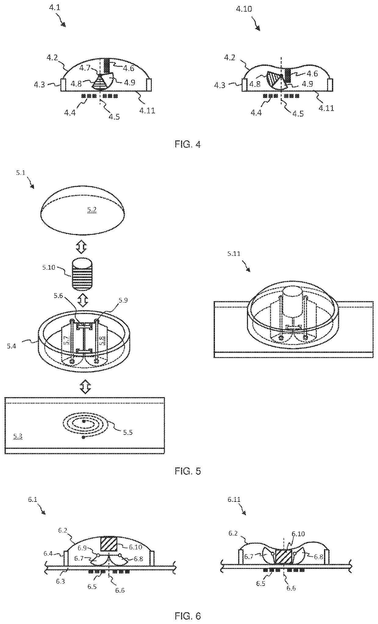
[0043]According to the present invention, the selective short-circuiting of a coil wound around a magnetic member may also be advantageously applied to push-buttons. This may allow robust user interface buttons to be created cost-effectively across sealed surfaces. For example, a first coil may be placed on one side of a sealed surface which allow passage of magnetic fields at a first frequency. A magnetic member, for example a ferrite member, with a second coil wound around it, may be located at the other side of said sealed surface, and may couple or guide magnetic flux emanating from said first coil. The terminals of the second coil may be either connected together, i.e. short circuited, or open-circuit. When the terminals are open circuit, magnetic field from the first coil may couple with the magnetic member in such a manner that the amount of inductance measured for the first coil increases. However, when the terminals of the second coil are short-circuited, coupling of the magnetic field generated by said first coil with the magnetic member may be adversely affected, resulting in a decrease in measured inductance for said first coil. A dome structure may be placed over said magnetic member and second coil, and used to short-circuit the terminals of the second coil. For example, a conductive member may be attached to the apex of said dome structure in such a manner that it connects the two terminals of the second coil together when the dome is pressed with sufficient force to cause it to snap through. Thereby, the snap through event may be discerned as a sudden decrease in inductance of the first coil. As an alternative, said dome structure itself may be fashioned out of conductive material, and used to short-circuit said second coil terminals when the dome is pressed to snap through.

Problems solved by technology

However, if a user applies more than a specific amount of force to said magnetic or flexible members, the flexible member may suddenly deflect downwards, also known as snapping through.
When less than said specific amount of force is applied to the push button structure, said dome structure remains more or less closed, and may cause significant eddy current losses, reducing said coil structure inductance.

Method used


Image

  • Touch and stylus sensing
  • Touch and stylus sensing
  • Touch and stylus sensing

Examples


Embodiment Construction

[0096]In FIG. 1A an exemplary inductive sensing based push button embodiment of the present invention is depicted at 1.1. A users finger 1.2, or another engaging object or device, may apply pressure or force to a magnetic member, for example a ferrite member, 1.3, or to material attached to member 1.3. The latter may be supported and held in place by a flexible member 1.4, which may be resilient in nature and deflect downwards when pressed. If sufficient force or pressure is applied to member 1.3, or to material attached to it, and thereby to flexible member 1.4, the latter may suddenly give way and substantially deflect downwards, known as snapping through. Members 1.3 and 1.4 are located over a conductive dome structure 1.5, which in turn is located over a coil or inductive structure (not shown), wherein said coil may experience eddy current losses due to dome 1.5, which may result in a decreased inductance measured by an inductive sensing circuit (not shown), for example a charge...


PUM


Abstract

A dual user interface trackpad that utilize capacitive sensing to detect user proximity and / or touch and inductive sensing to detect stylus input, allowing a user to select specific content or a window on an associated display with touch, to reposition and manipulate the selected content or window with touch to facilitate more convenient entry of additional content amongst the selected content or window using the stylus, and to indicate completion of the entry of content with another touch and / or proximity event on or near the trackpad.

Description

CROSS-REFERENCE TO RELATED APPLICATION[0001]The present application is a Continuation application of U.S. Ser. No. 16 / 220,124, filed Dec. 14, 2018, which claims priority from South Africa application ZA 2017 / 08524, filed on Dec. 15, 2017, and South Africa application ZA 2018 / 03620, filed on May 31, 2018, the contents of which are hereby incorporated by reference into this application.BACKGROUND OF THE INVENTION[0002]Inductive sensing buttons which utilize conductive or magnetic material to influence the inductance of a measured structure are known in the art. For example, in U.S. Pat. No. 8,847,892 laminar structures which use either a bulk conductor or magnetic material being pushed closer to a sensing coil are disclosed. In US 2011 / 0187284 inductive sensing buttons with a metal target located below an outer surface are taught, wherein the outer surface is depressed by a user, causing the metal target to be pushed towards a sensing coil.[0003]When a metal target is pressed closer t...

Claims


Application Information

Patent Timeline
Patent Type & Authority Applications(United States)
IPC IPC(8): G06F3/041G06F3/044G06F3/046G06F3/0354G06F3/0488G06F3/14G06F3/038
CPCG06F3/0416G06F3/044G06F3/046G06F3/03545G06F3/03547G06F3/04883G09G2354/00G06F3/038G06F3/1462G06F2203/04104G06F2203/04108G06F2203/04106G09G2370/06G06F3/1423
Inventor BRUWERBRAND, TOBIAS GERHARDUSVAN WYK, JACOBUS DANIEL
Owner AZOTEQ HLDG LTD
Why Eureka
Try Eureka