Eureka AIR delivers breakthrough ideas for toughest innovation challenges, trusted by R&D personnel around the world.

Cooling assembly for cooling a rotating machine

Pending Publication Date: 2021-03-18
DANA BELGIUM
View PDF0 Cites 0 Cited by
  • Summary
  • Abstract
  • Description
  • Claims
  • Application Information

AI Technical Summary

Benefits of technology

The present patent is about a cooling system for rotating machines, particularly electric generators and motors, that helps to prevent overheating. The system includes a cooling jacket that surrounds the machine and has liquid inlets and outlets. The liquid flows inside the jacket and can be directed towards the ends of the machine using liquid jet devices. The system is designed to provide a homogeneous flow of liquid cooling that avoids hot spots and ensures efficient cooling. The technical effect of this patent is to provide a more efficient and effective cooling system for rotating machines that can prevent overheating and improve performance.

Problems solved by technology

This effect is generally not avoidable due to limited efficiencies.
Also, higher power levels of electric motors and generators lead to higher operational temperatures.

Method used


Image

  • Cooling assembly for cooling a rotating machine
  • Cooling assembly for cooling a rotating machine

Examples


Embodiment Construction

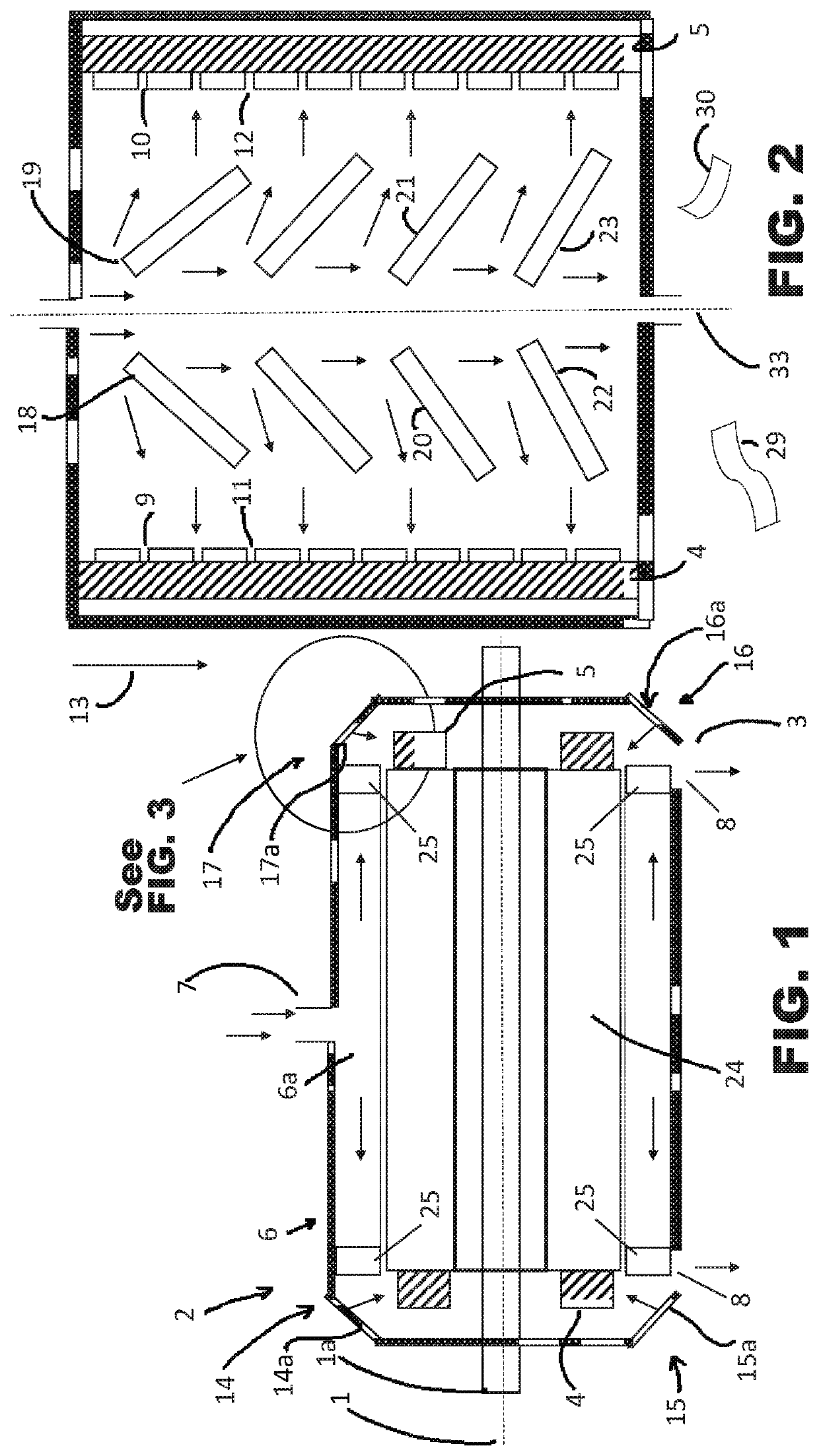
[0035]FIG. 1 shows in a longitudinal cross section an electric motor with a rotational axis 1, shaft la, and a central rotor surrounded by a stator 24, wherein the stator comprises electric windings. Only the end windings 4, 5 on both axial ends 2, 3 of the machine are shown. Further, the stator 24 is surrounded by a cooling jacket 6 which comprises a hollow cylindrical space 6a between an outer and an inner cylinder wall. The hollow cylinder space 6a is filled with a cooling liquid, for example a cooling oil. At the circumference of the cooling jacket 6, a liquid inlet 7 and further liquid outlets 8 are shown. As depicted in FIG. 1, the outlets 8 may be disposed at or near the axial ends of the electric motor. The arrows inside the cooling jacket 6 show in a symbolic way exemplary directions of the flow of the cooling liquid.

[0036]The cooling liquid is flowing through the cooling jacket partially in a circumferential direction and partially in axial directions. At the axial ends 2,...


PUM


Abstract

A cooling jacket surrounding the stator of an electric machine, having an inlet and a plurality of outlets disposed at ends of the cooling jacket, distributed in circumferential direction and configured to create liquid jets exiting the cooling jacket in a radial direction towards end windings at the axial ends of the machine. Coolant liquid flow guiding elements within the cooling jacket are configured so as to create a circumferentially homogeneous or more homogenous axial liquid flow towards the liquid outlets and / or towards the liquid jet devices.

Description

CROSS-REFERENCE TO RELATED APPLICATION[0001]The present application claims priority to European Patent Application No. 19197115.9, entitled “COOLING ASSEMBLY FOR COOLING A ROTATING MACHINE”, and filed on Sep. 12, 2019. The entire contents of the above-listed application are hereby incorporated by reference for all purposes.BACKGROUND AND SUMMARY[0002]Rotating machines like electric generators, electric motors or other kinds of motors usually are converting one form of energy into another form. Part of the converted energy usually is also converted into thermal energy thereby raising the temperature of the rotating machine. This effect is generally not avoidable due to limited efficiencies. Improvements in performance of all kinds of machines, including electric motors used in domestic appliances or in automotive technology, lead to higher requirements and higher thermal loads. Also, higher power levels of electric motors and generators lead to higher operational temperatures.[0003]A...

Claims


Application Information

Patent Timeline
IPC IPC(8): H02K5/20H02K5/18H02K9/19
CPCH02K5/20H02K9/19H02K5/18
Inventor VANHEE, STEVEN
Owner DANA BELGIUM
Why Eureka
Eureka Blog
Learn More