Electron source for a vacuum pressure measuring device

Inactive Publication Date: 2010-03-18
INFICON GMBH
View PDF2 Cites 11 Cited by
  • Summary
  • Abstract
  • Description
  • Claims
  • Application Information

AI Technical Summary

Benefits of technology

[0016]An advantageous effect of the invention is the prevention of gas or ion-based interactions between the electron source region and the ionization or measuring region. This is the prerequisite for the

Problems solved by technology

Electron sources with field emitters (field emission) furthermore have also been proposed for vacuum pressure measurements, which, with respect to the conditions of application and / or to the production expenditure, have so far not become commercially widely established.
Fast venting of the arrangement, for example when opening a process vacuum chamber for loading workpieces to be treated, is especially problematic since the oxygen intrusion leads to the destruction of the active, electron emitting thermionic cathode (cf incandescent lamp).
Further problems are generated in case of contaminations, especially through forepumps contaminated with operating fluid, such as sliding vane rotary pumps.
Aggressive process and etching gases frequently utilized today, such as for example silane and gases based on chlorine and fluorine, are also highly problematic.
When using very aggressive process gases, it is therefore customary to protect vacuum measuring devices based on ionization, which are necessary for the base pressure measurement, against the process with a valve, such as for example an all-metal vane, which leads to considerable additional costs and makes the application feasibilities difficult and limited.

Method used


Image

  • Electron source for a vacuum pressure measuring device
  • Electron source for a vacuum pressure measuring device
  • Electron source for a vacuum pressure measuring device

Examples


Embodiment Construction

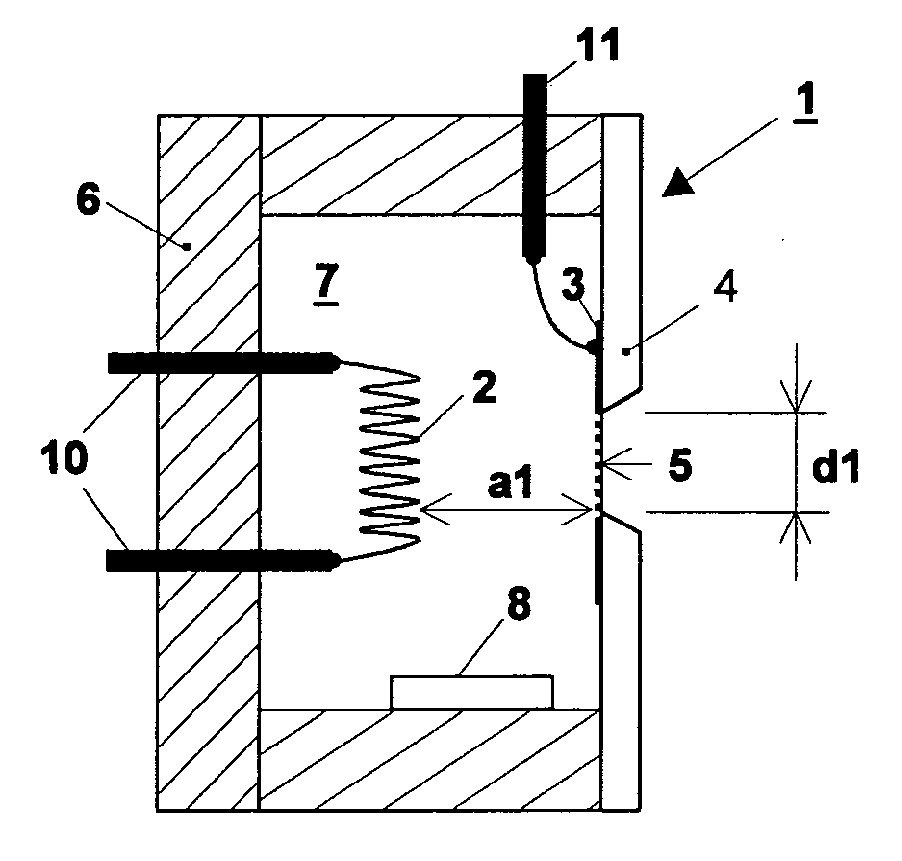
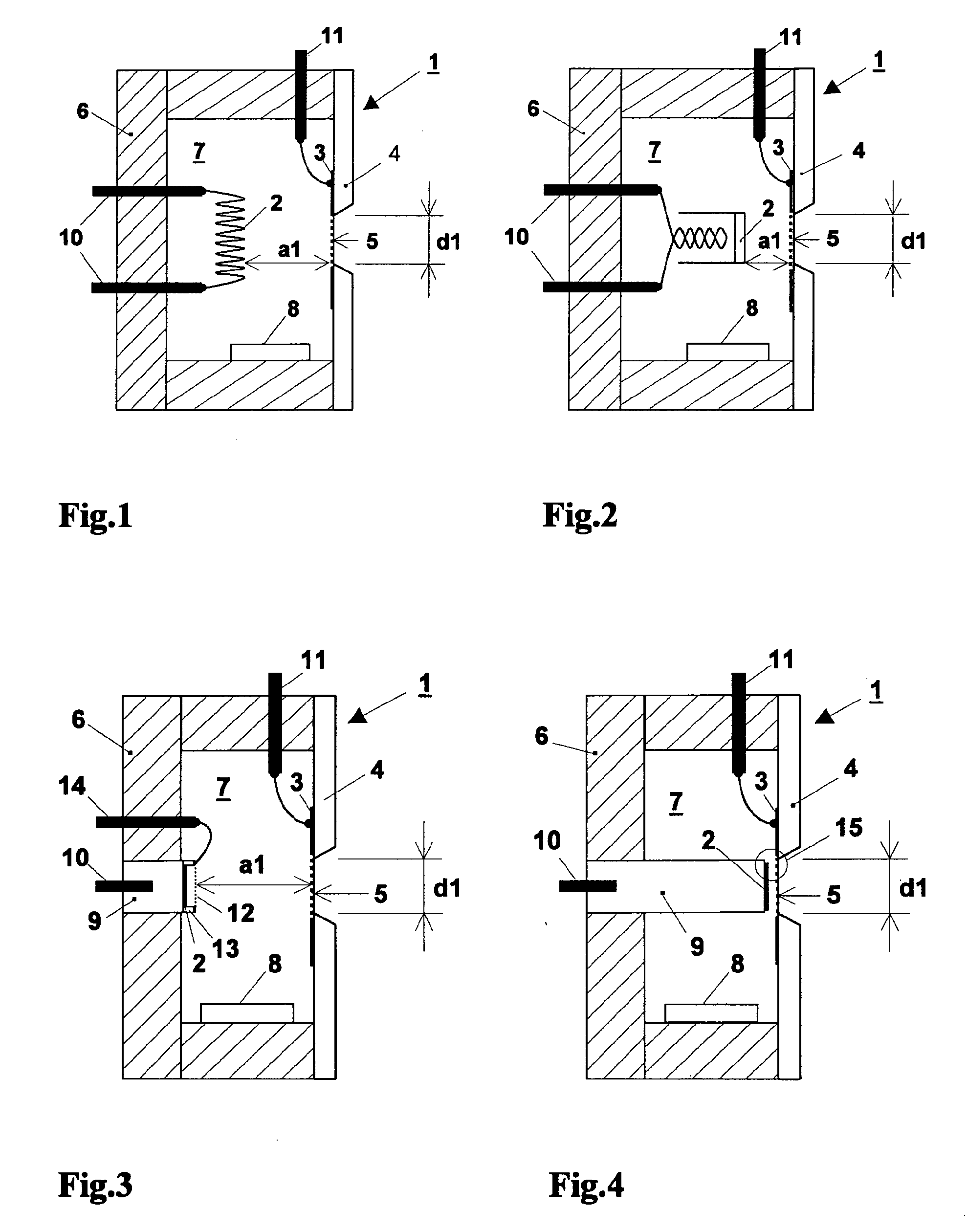
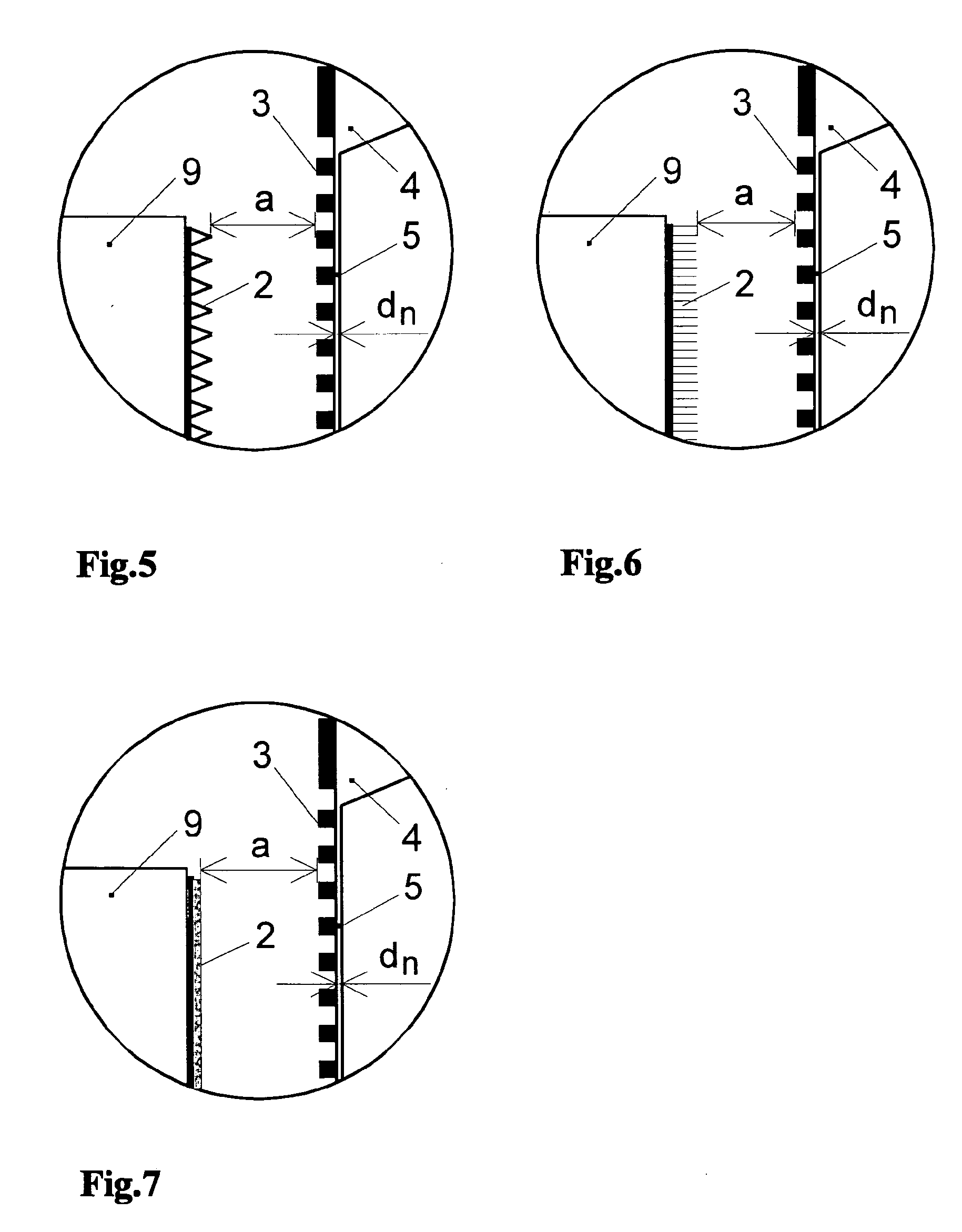
[0036]Preferred embodiments of the electron source 1 according to the invention will be described in the following in greater detail and by example in conjunction with FIGS. 1 to 7. The electron source 1 comprises an insulating housing 6, for example of a ceramic, which encompasses a vacuum volume 7 and on one side on the housing wall includes a nanomembrane 5 of thickness dn and the dimensions d1 with square, circular or rectangular (therein in the second side dimension freely selectable) membrane embodiment, which separates the vacuum volume 7 gas-tight from the surrounding. The surrounding is a further vacuum zone which forms a portion of a vacuum pressure measuring device or of a mass spectrometer, which, in order to fulfill its measuring task, communicates with a vacuum chamber in which a vacuum process takes place. The membrane 5 is advantageously disposed on a membrane carrier 4 which advantageously can directly form a portion of the wall of the housing 6. The vacuum within t...


PUM


Abstract

A vacuum pressure measuring device with an electron source has a reaction zone for forming ions by impact ionization, wherein the electron source communicates with the reaction zone via a passage for the electrons. The electron source is surrounded by an insulating housing with a vacuum chamber, and a partition part is designed as a membrane carrier, carrying a nanomembrane at least in one section, the membrane separating the vacuum chamber from the outer region in a gastight manner and being at least partially designed to be electron-permeable. The vacuum chamber has a cathode for the emission of electrons. In the region of and / or on the nanomembrane, an anode arrangement is provided such that electrons are conducted against the nanomembrane and at least partially through it. The nanomembrane abuts the vacuum chamber of the vacuum pressure measuring device.

Description

FIELD AND BACKGROUND OF THE INVENTION[0001]The invention relates to a vacuum pressure measuring device with an electron source and with a reaction zone for the formation of ions through impact ionization.[0002]The invention relates, in particular, to vacuum pressure measuring engineering or to vacuum pressure measuring devices based on the ionization of gas molecules for the measurement of total pressure (ionization manometer) as well as also for the measurement of partial pressure (mass spectrometer).[0003]For the ionization of the gas molecules in a vacuum pressure measuring device for the measurement of total pressure (ionization manometer) as well as also for the measurement of partial pressure (mass spectrometer) an electron source is necessary, located in the immediate proximity to the ionization volume as is known in prior art. Under measuring conditions in vacuum pressure ranges from less than 1 Pa (10−2 mbar), and with high pressure measuring tubes 1 to 2 decades higher, th...

Claims


Application Information

Patent Timeline
IPC IPC(8): G01L21/32H01J49/26
CPCG01L21/32G01L21/30G01L21/34
Inventor KNAPP, WOLFRAMWUEST, MARTIN
Owner INFICON GMBH
Why Eureka
Try Eureka