Supercharge Your Innovation With Domain-Expert AI Agents!

Multi-Axis Gripper For Lab Automation Robot

a lab automation robot and multi-axis technology, applied in the direction of manipulators, programmed manipulators, gripping heads, etc., can solve the problems of not providing rotation or rotation of the gripper relative to the x direction (e.g., rolling) and the adjustment of the gripper in these two rotatable components is not typically considered desirable or necessary, and the nest is often at least slightly unlevel

Active Publication Date: 2021-03-25
THERMO CRS
View PDF0 Cites 2 Cited by
  • Summary
  • Abstract
  • Description
  • Claims
  • Application Information

AI Technical Summary

Benefits of technology

The present invention relates to an improved gripper for lab automation robots that can reliably retrieve and deposit microtiter plates from nests that are not level relative to the gripper. This allows for continued operations using the relatively unlevel nests, without the need for a complete replacement of the robotic device. The invention provides a multi-axis gripper that can adjust its position in three dimensions, including translation and orientation, to compensate for unlevel nests. This results in more efficient and reliable retrieval and deposition of microtiter plates, reducing the risk of errors and improving the overall performance of the automated laboratory system.

Problems solved by technology

However, such robotic devices do not provide rotation of the gripper relative to the X direction (e.g., rolling) or rotation of the gripper relative to the Y direction (e.g., pitching), since the nests from / on which the microtiter plates are to be retrieved / deposited are typically presumed to be horizontally level relative to the gripper and, more particularly, relative to the fingers of the gripper, such that adjustability of the gripper in these two rotatable components is not typically considered desirable or necessary.
Despite this presumption, such nests are often at least slightly unlevel relative to the gripper.
As a result, the gripper may be unable to reliably retrieve a microtiter plate from the relatively unlevel nest or deposit a microtiter plate on the relatively unlevel nest.

Method used


Image

  • Multi-Axis Gripper For Lab Automation Robot
  • Multi-Axis Gripper For Lab Automation Robot
  • Multi-Axis Gripper For Lab Automation Robot

Examples


Embodiment Construction

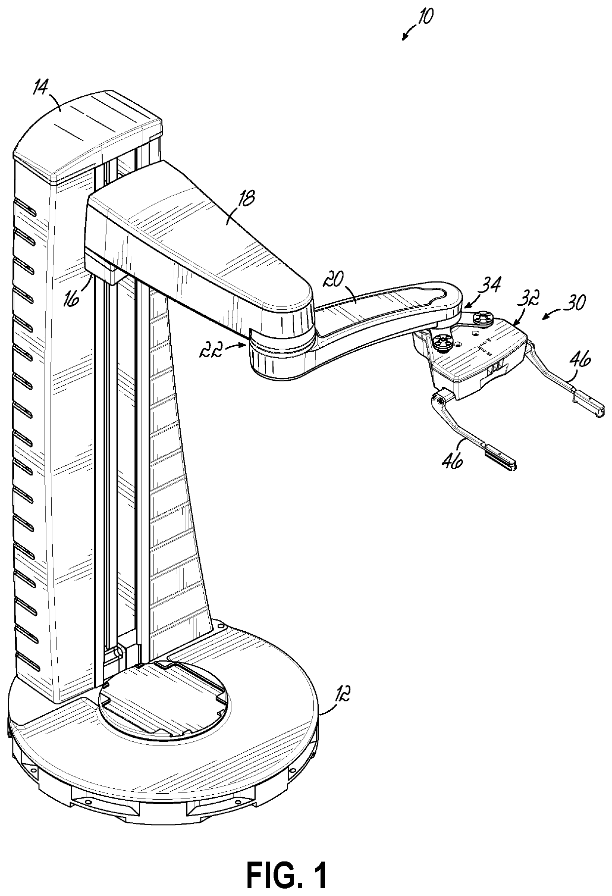
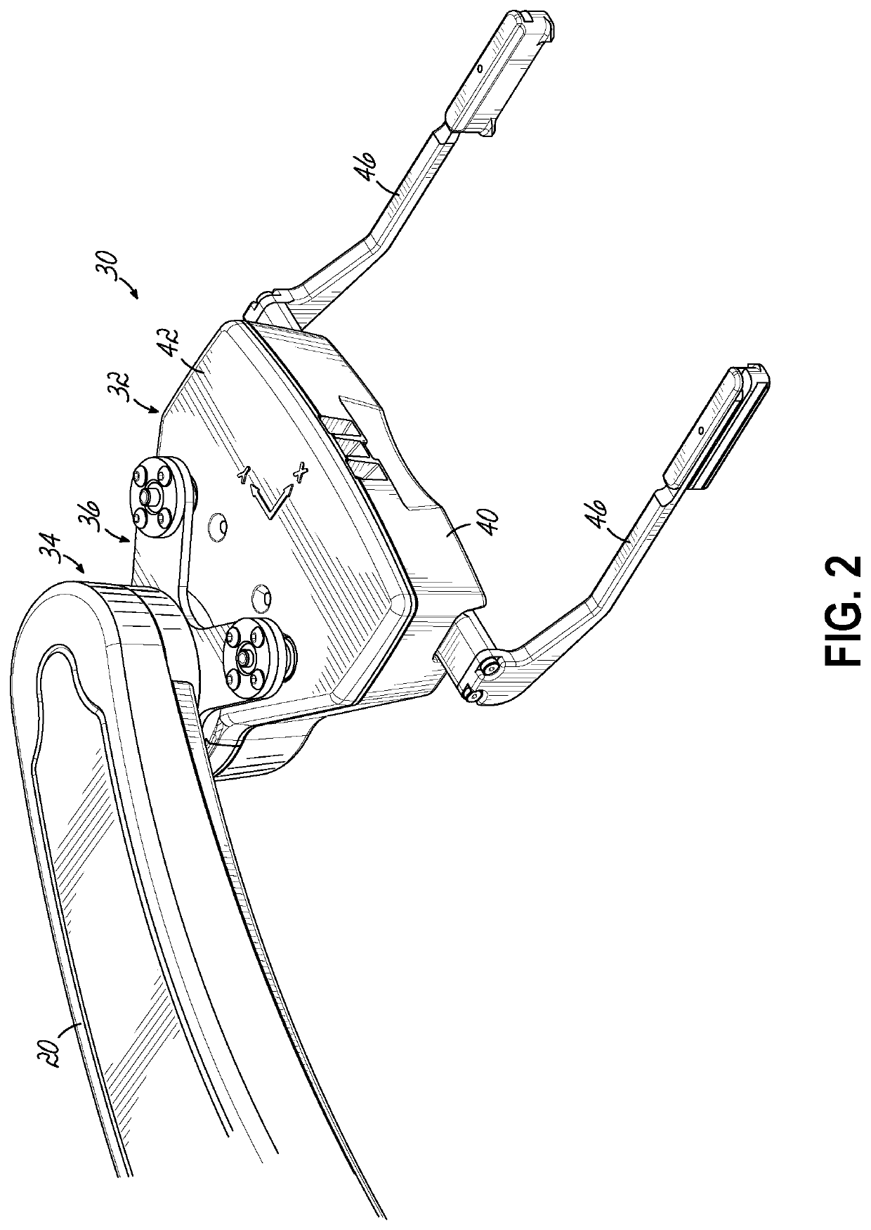
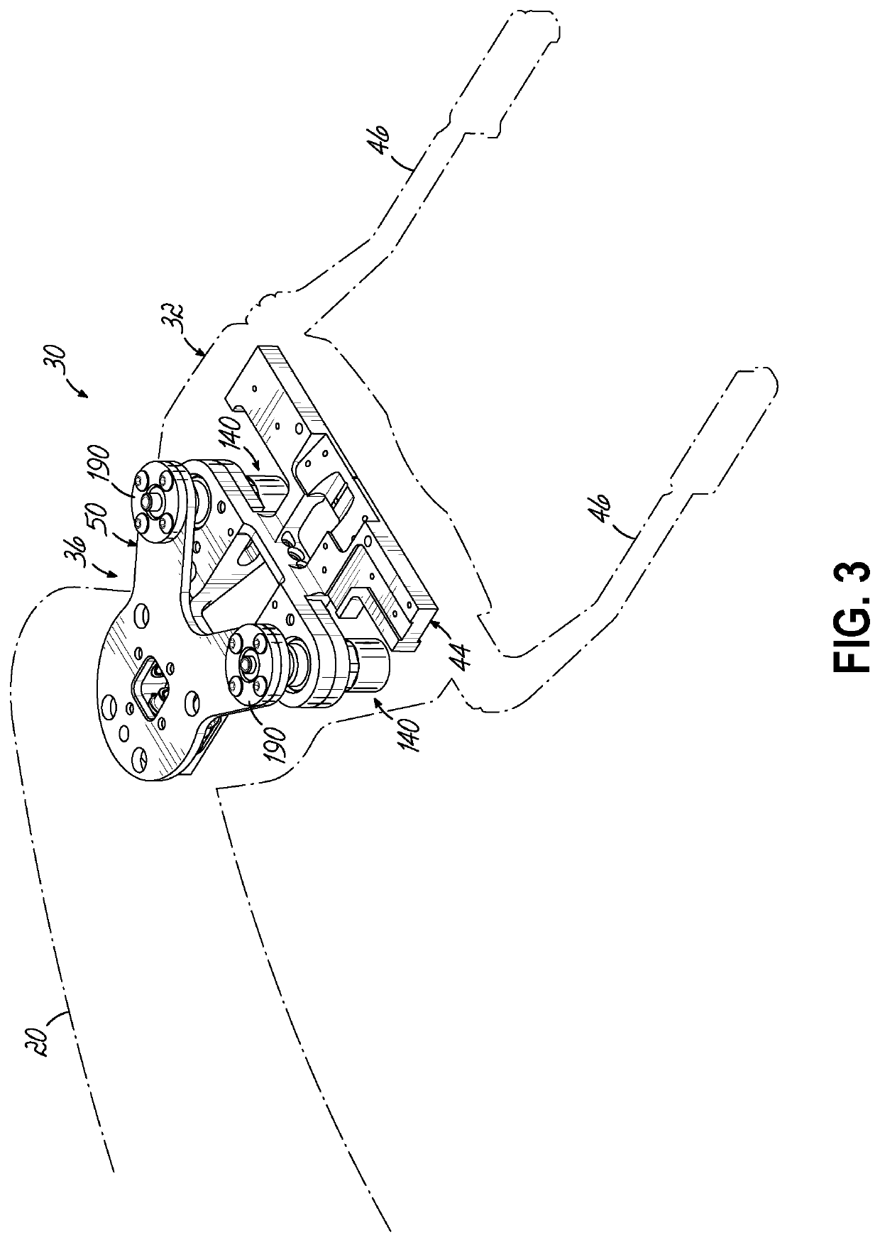
[0020]With reference to FIG. 1, an exemplary robotic device 10 configured to perform at least one scientific process is shown in accordance with one embodiment of the present invention. The robotic device 10 may be a SCARA type robotic device, such as that sold by Thermo Fisher Scientific, Inc. under the trademark Spinnaker XT. Other types of robotic devices may be used, such as an articulated robotic device, a spider robotic device, or any other suitable types of robotic device. The illustrated robotic device 10 includes a stationary base 12, a swiveling tower 14 rotatably mounted to the stationary base 12 about a first vertical axis (not shown), an elevator 16 and accompanying arm 18 vertically translatably mounted to the tower, an articulating forearm 20 coupled to the arm 18 at an elbow joint 22 and pivotable relative thereto about a second vertical axis (not shown), and a wrist assembly 30 including a multi-axis gripper 32 operatively coupled to the forearm 20 at a wrist joint ...


PUM


Abstract

A lab automation robot is provided including a stationary base, a swiveling tower rotatably mounted to the stationary base about a first vertical axis, an arm vertically translatably mounted to the tower, an articulating forearm coupled to the arm at an elbow joint and pivotal relative thereto about a second vertical axis, and a wrist assembly including a multi-axis gripper operatively coupled to the forearm at a wrist joint and rotatable relative thereto about a third vertical axis. The gripper is further rotatable relative to at least the forearm about a first horizontal axis and about a second horizontal axis.

Description

CROSS-REFERENCE TO RELATED APPLICATION[0001]The present application claims the filing benefit of U.S. Provisional Application Ser. No. 62 / 904,732, filed on Sep. 24, 2019, the disclosure of which is incorporated herein by reference in its entirety.FIELD OF THE INVENTION[0002]The present invention relates generally to automated laboratory systems for performing scientific processes such as assays and, more particularly, to grippers for lab automation robots of such automated laboratory systems.BACKGROUND OF THE INVENTION[0003]Conventional automated laboratory systems include a lab automation robot and a variety of instruments positioned therearound. The lab automation robot may be, for example, a selective compliance articulated robot arm (SCARA) type, and the instruments may include, for example, a liquid handler, an incubator, a reagent dispenser, a sealer, a microplate spectrophotometer, a thermocycler, a thermocycler controller, or any other suitable instrument for performing a de...

Claims


Application Information

Patent Timeline
IPC IPC(8): B25J15/08B25J18/00B25J17/02
CPCB25J15/08B25J17/025B25J18/00B25J15/0253B25J9/042B25J17/0275B25J17/0283
Inventor RIFF, MICHAEL PAULWITTCHEN, JONATHANDARNEL, GARYJOHNSON, STEPHEN WAYNE
Owner THERMO CRS
Features
  • R&D
  • Intellectual Property
  • Life Sciences
  • Materials
  • Tech Scout
  • Unparalleled Data Quality
  • Higher Quality Content
  • 60% Fewer Hallucinations
Learn More