Device for artificial insemination, gynaecological examination of the vagina and the cervix, and to assist with uterine treatments and sample collection in livestock

a technology of gynaecological examination and artificial insemination, which is applied in the field of design and construction of gynaecological devices, can solve the problems of animal injury, no longer visible front end of the operator, and inability to solve the problem of preventing so as to facilitate the insertion of the artificial insemination device, minimise the risk of the device being obstructed, and improve the comfort of the animal

Pending Publication Date: 2021-04-01
INOVET TECH
View PDF4 Cites 0 Cited by
  • Summary
  • Abstract
  • Description
  • Claims
  • Application Information

AI Technical Summary

Benefits of technology

[0044]This location of the camera facilitates the insertion of the artificial insemination device inside the reproductive tract of the animal. This improves the comfort of the animal during use of the device. For example, placing the camera inside the sleeve minimises the risks of the device being obstructed by folds in the reproductive tract of the animal.
[0045]A further advantage is that the device comprises transmission means for transmitting the images captured by the camera to a remote display screen, whereby the transmission means are integrated inside the distal end of the guiding sleeve.
[0046]This configuration enables optimal transfer of captured images to the remote display (such as a smartphone), even when the device is inserted deep or entirely within the reproductive tract of the animal.

Problems solved by technology

This solution, however, has its drawbacks.
One disadvantage lies in the fact that, when the insemination device is inserted into the animal, its front end is no longer visible to the operator, who must therefore work by sense of touch alone.
This requires a degree of technical skill that can only be achieved after a lengthy training process and that can, in unskilled hands, result in injury to the animal.
In addition, it can sometimes be difficult to locate the entry point to the cervix, which itself may have several annular rings that can be narrow and difficult to traverse.
The insertion of the insemination device can distress the animal and cause the vaginal and cervical muscles to contract, temporarily preventing the device from moving further.
Another disadvantage lies in the fact that “blindly” inserting the insemination device into the reproductive tract of the animal might cause injury if its pointed end scrapes against the vaginal mucosa.
This may also occur if the animal moves unexpectedly during the procedure.
Another disadvantage lies in the fact that the operator must insert a hand and arm into the rectum of the animal, in order to hold and manoeuvre the cervix through the rectal wall so that the insemination device can be inserted from the cervix to the uterine corpus, which is uncomfortable for the animal, particularly since the operation can last a long time.
Another disadvantage lies in the fact that the operator must insert a hand and arm into the rectum of the animal, in order to hold and manoeuvre the cervix through the rectal wall so that the insemination device can be inserted from the cervix to the uterine corpus, which is uncomfortable for the operator, particularly since the operation can last a long time, and if repeated several times a day can result in chronic musculoskeletal pain for the operator.
However, due to their larger diameter, they are uncomfortable for the animal and lack the manoeuvrability to traverse the cervix of some animals.

Method used


Image

  • Device for artificial insemination, gynaecological examination of the vagina and the cervix, and to assist with uterine treatments and sample collection in livestock
  • Device for artificial insemination, gynaecological examination of the vagina and the cervix, and to assist with uterine treatments and sample collection in livestock
  • Device for artificial insemination, gynaecological examination of the vagina and the cervix, and to assist with uterine treatments and sample collection in livestock

Examples


second embodiment

5.2 Second Embodiment

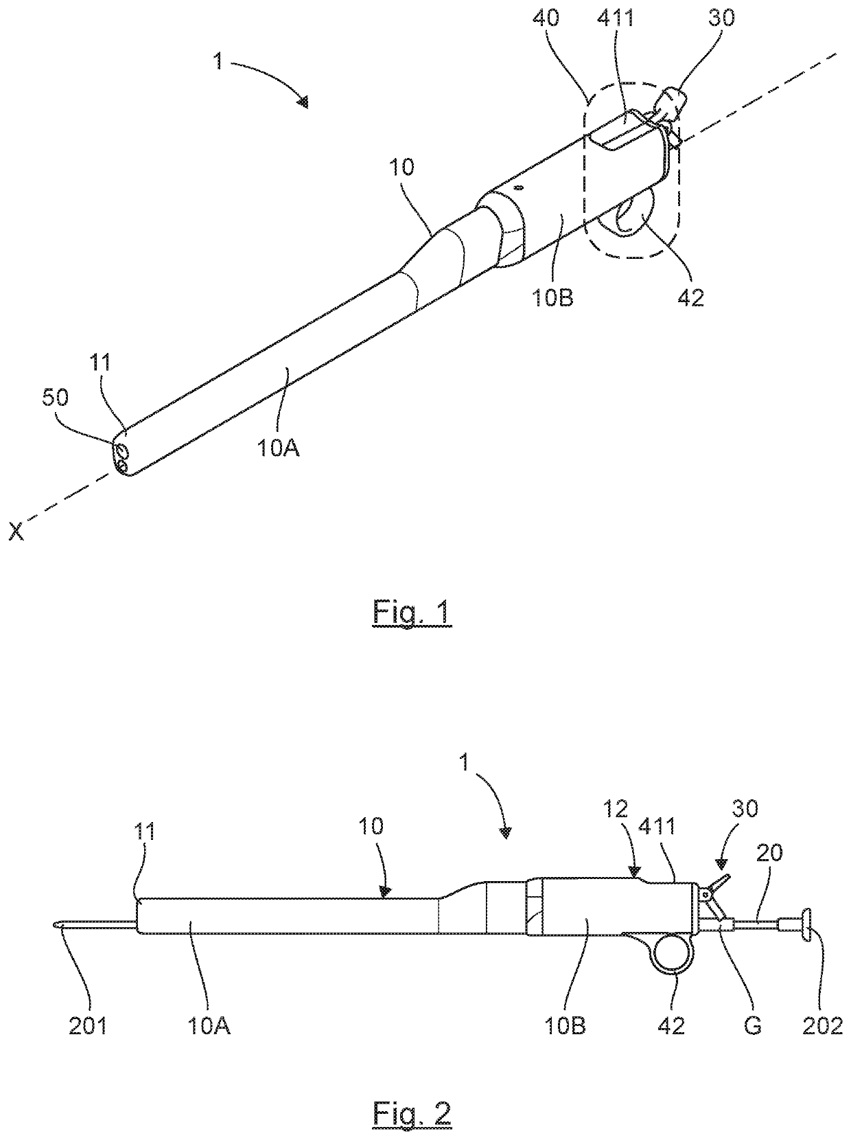
[0158]FIG. 10 is a perspective view of a device for the artificial insemination, vaginal and cervical examination, and uterine treatment and sample collection for livestock, according to a second specific embodiment of the invention.

[0159]This second embodiment differs from the first in the structure of its guiding sleeve and the structure of its gripping assembly.

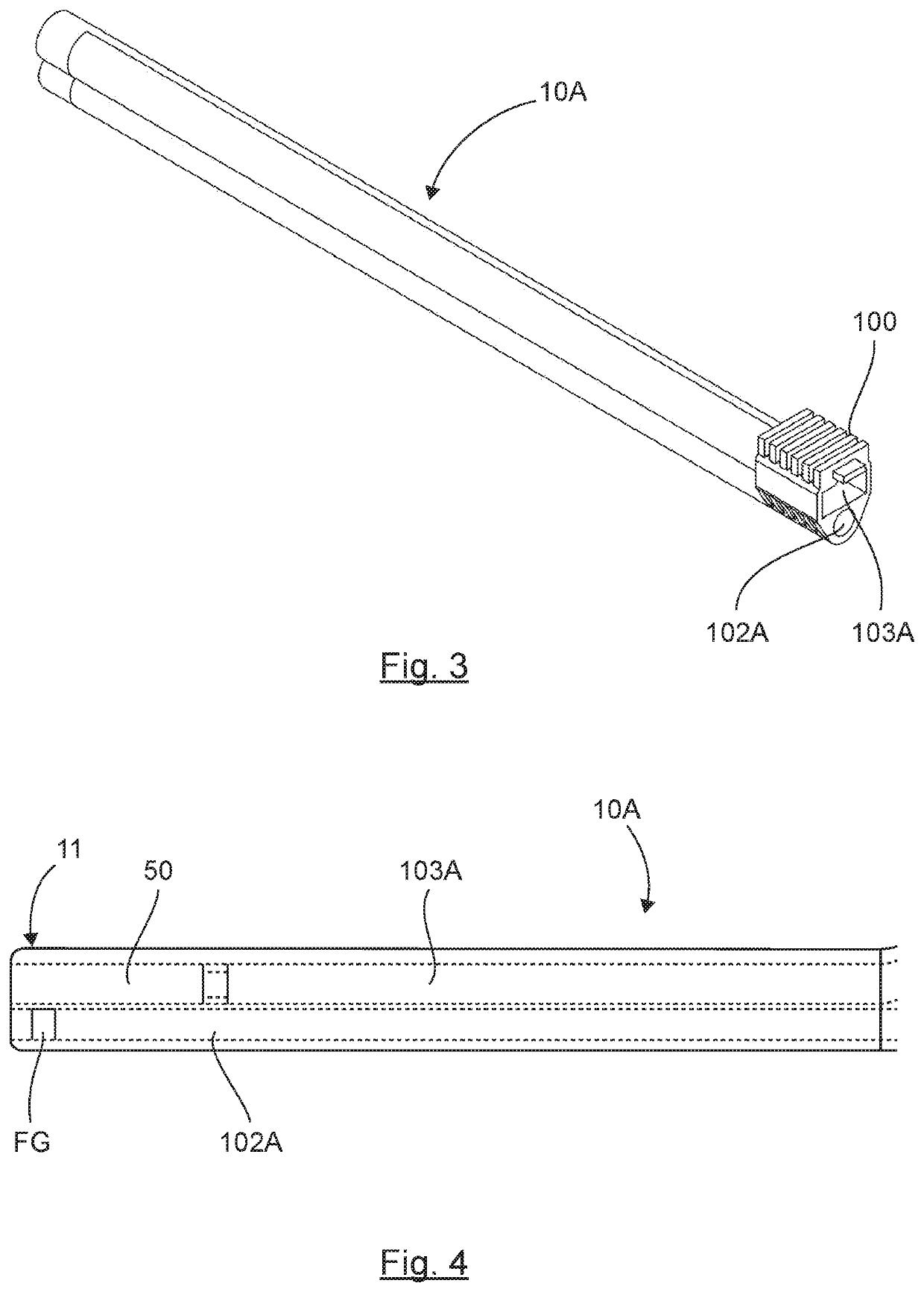
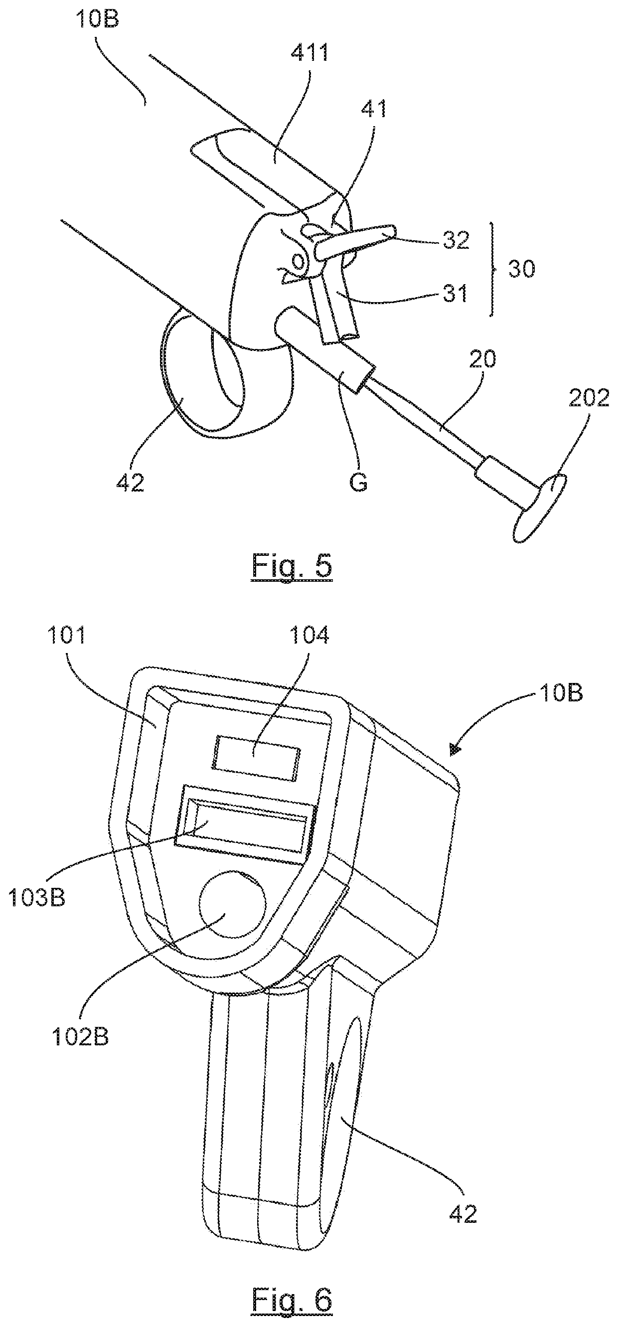
[0160]In this second embodiment, the device 1′ comprises a guiding sleeve 10′ formed of a hollow cylindrical tube as a single element, with a proximal end 11′ designed for insertion into the vagina of the animal, and a distal end 12′ designed to be operated by the user during an insemination procedure.

[0161]The insemination gun 20′ is identical to that described in the first embodiment, and thus comprises a front end 201′, intended to be positioned in the cervix of the animal, and a rear end 202′, intended to be used by the operator to inject the contents of a semen straw into the uterus of the animal....


PUM


Abstract

A device for artificial insemination, gynaecological examination of the vagina and the cervix, intra-uterine treatments and uterine sample collection in livestock. The device includes: a guiding sleeve having a proximal end for being positioned in the reproductive system of the animal and a distal end for being handled by the user; a gynaecological instrument, such as an insemination gun, an insemination or treatment catheter, or a sample-collection swab, slidingly housed in the guiding sleeve, the instrument being capable of being operated by the user at the rear end thereof, located on the side of the distal end of the guiding sleeve, in order for the front end thereof to lead through an opening located at the proximal end of the guiding sleeve so as to allow the insemination, treatment or sample collection. The guiding sleeve has a blocking element for blocking the sliding of the instrument inside the guiding sleeve.

Description

1 FIELD OF INVENTION[0001]This invention relates to the design and construction of gynaecological devices particularly, but not exclusively, intended for the artificial insemination, examination of the vagina and cervix, or veterinary treatment of livestock such as cows or mares.2 STATE OF THE ART[0002]Artificial insemination of livestock, such as cows or mares, is widely used for reproduction.[0003]This biotechnology allows the rapid and widespread diffusion of male reproductive genes in a manner known per se and in optimal sanitary conditions.[0004]Artificial insemination thus helps improve animal performance and promote the exchange of genetic material.[0005]At present there are a number of artificial insemination techniques, one of which entails the use of an insemination device that is inserted into the vagina of the animal by an operator so as to reach the cervix, traverse it, and inject a semen dose contained in a straw into the uterus.[0006]In general, an insemination device...

Claims


Application Information

Patent Timeline
Patent Type & Authority Applications(United States)
IPC IPC(8): A61D19/02A61B1/00A61B1/05A61B1/06A61B1/303
CPCA61D19/027A61B1/00016A61B1/303A61B1/0676A61B1/05A61B1/307A61D17/002A61D19/02
Inventor POIRIER, ANTOINE
Owner INOVET TECH
Why Eureka
Try Eureka