Robot control system

Pending Publication Date: 2021-04-01
FANUC LTD
View PDF9 Cites 0 Cited by
  • Summary
  • Abstract
  • Description
  • Claims
  • Application Information

AI Technical Summary

Benefits of technology

The present invention relates to a robot control system that can sense when the robot is in a safe area and move it to a safer area if there is an unexpected situation. This prevents damage to equipment and ensures continuous and safe execution of the process. The technical effect of this invention is to enhance the safety and reliability of the robot control system in process environments.

Problems solved by technology

It is conceivable that in a case where a robot performs a process while following an article moved by a delivery apparatus, the robot fails to perform the process in time.
At this point, there is a probability that equipment is damaged before completion of the process by the robot due to fitting failure or biting of the pin.

Method used


Image

  • Robot control system
  • Robot control system
  • Robot control system

Examples


Embodiment Construction

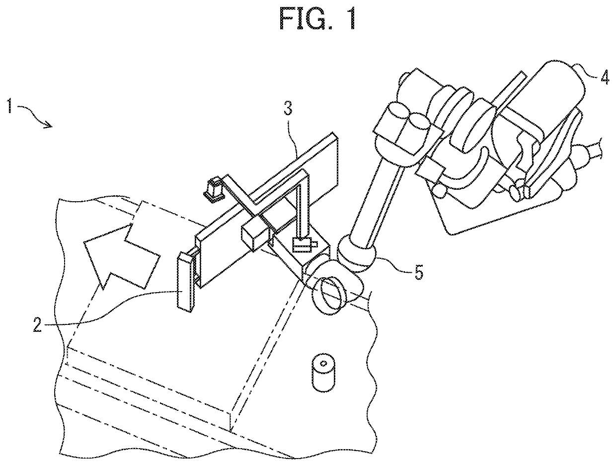
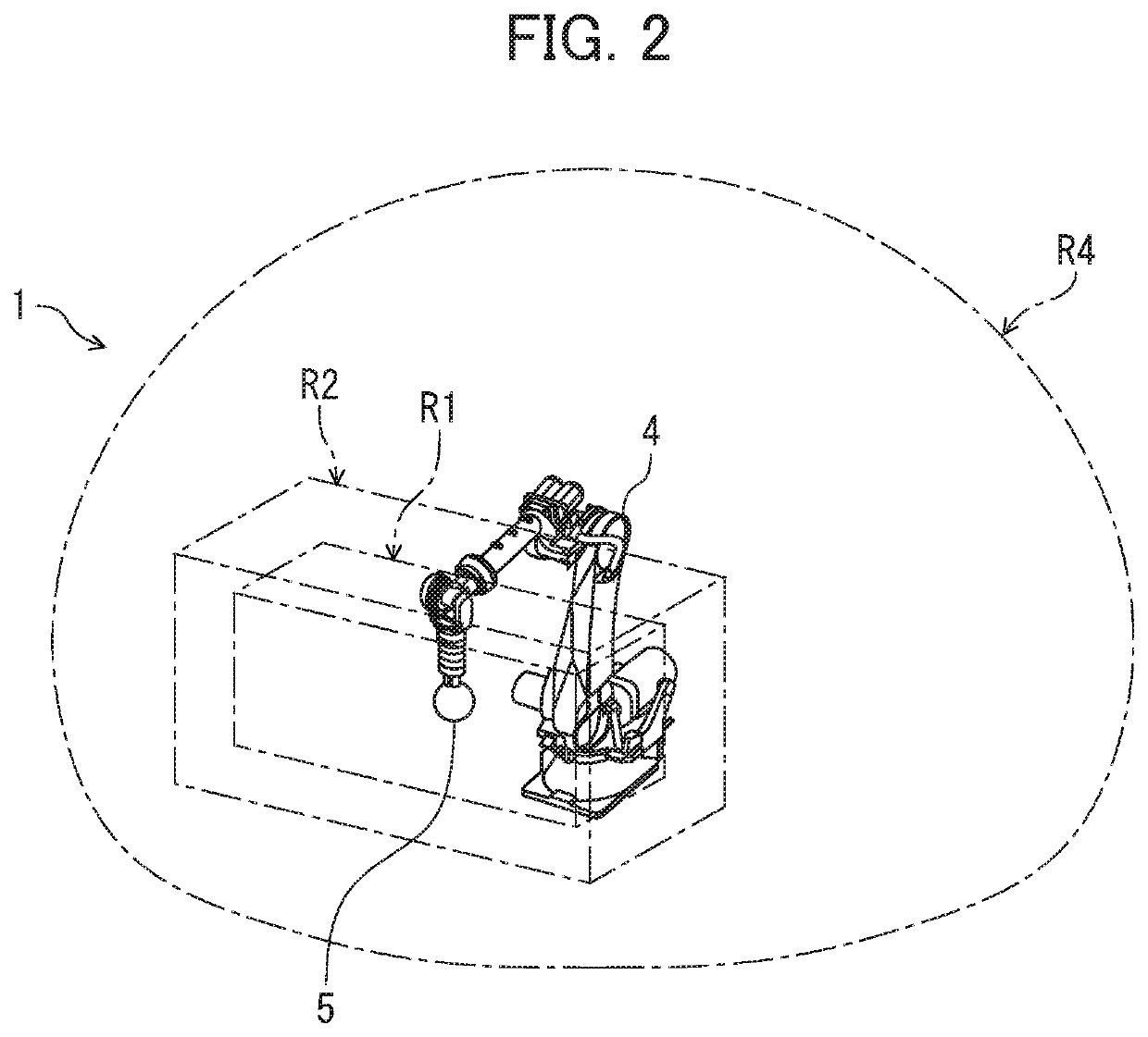
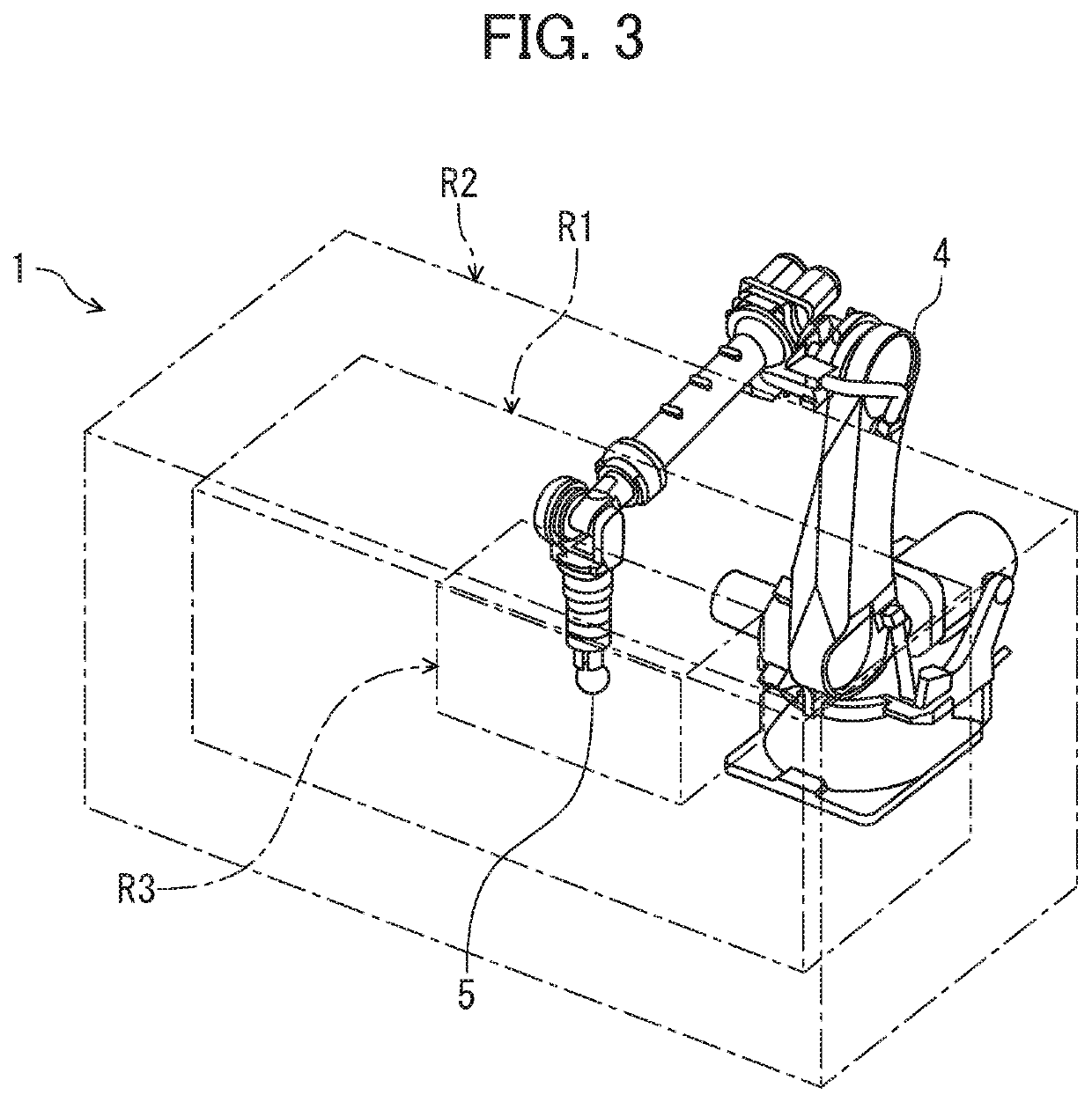
[0018]Hereinafter, a robot control system according to one embodiment will be described with reference to FIGS. 1 to 4. The robot control system of the present embodiment relates to, for example, a system provided on a production line to control a robot (an industrial robot) that performs a process for a delivered process target such as an article.

[0019]Specifically, the robot control system 1 of the present embodiment includes, as shown inFIG. 1, a robot 4 that performs, e.g., the process of assembling a door 3 with the process target 2 such as an automobile body (not shown) and a control unit that controls drove of the robot 4.

[0020]The robot 4 is, for example, formed in an articulated shape, and includes one or more visual sensors provided at a movable arm and a tool (a working apparatus) 5 that is attached to the arm to perform a predetermined process for the process target 2.

[0021]The control unit controls drive of the robot 4 to perform. the process for the process target 2, a...


PUM


Abstract

To provide a robot control system that performs a process by a robot for a continuously-moving process target or a repeatedly-moving / stopped process target, the robot control system being configured so that even in a case where the robot process cannot be properly performed in the robot control system, disadvantages such as occurrence of damage of equipment can be avoided by sensing of such failure in the robot process. The robot control system includes a robot that performs a process for a process target, a control unit that controls drive of the robot, a first area setting unit that sets a first area where the process is performed for the process target, and a second area setting unit that sets a second area outside the first area such that the robot performs a retraction motion when a working apparatus provided at the robot moves out of the first area and enters the second area while the robot is following the moving process target.

Description

[0001]This application is based on and claims the benefit of priority from Japanese Patent Application No. 2019-174975, filed on 26 Sep. 2019, the content of which is incorporated herein by reference.BACKGROUND OF THE INVENTIONField of the Invention[0002]The present invention relates to a robot control system.Related Art[0003]Typically, in a case where an industrial robot performs a process for a process target such as an article delivered on, e.g., a production line, it is important to control, with high accuracy, drive and stop (a stop position) of the robot for the delivered process target.[0004]For example, Japanese Unexamined Patent Application, Publication No. 2002-018754 discloses a “robot apparatus that grips a relatively-moving target object, the robot apparatus including a gripping section having a gripping mechanism that grips the target object and configured such that the gripping mechanism is movable, an imaging section fixed movably together with the gripping mechanism...

Claims


Application Information

Patent Timeline
IPC IPC(8): B25J9/16B25J9/00
CPCB25J9/1666B25J9/1674B25J9/0093B25J9/1602B25J9/1664G05B19/0428B25J9/1676G05B2219/49237
Inventor OOBA, MASAFUMI
Owner FANUC LTD
Why Eureka
Try Eureka