Lens driving device and camera module including same

a technology of driving device and camera module, which is applied in the direction of mountings, printing, instruments, etc., can solve the problems of increasing power consumption, reducing control characteristics, and reducing driving force, so as to reduce power consumption, reduce friction torque, and improve driving power

Pending Publication Date: 2021-04-01
LG INNOTEK CO LTD
View PDF2 Cites 2 Cited by
  • Summary
  • Abstract
  • Description
  • Claims
  • Application Information

AI Technical Summary

Benefits of technology

[0029]The lens driving device and the camera module including the same according to the embodiment have a technical effect of solving the problem of friction torque generation during zooming.
[0030]For example, in the embodiment, the lens assembly is moved along the pin, while the ball accommodation part is provided inside the lens assembly so that the pin is in point contact with the ball, thereby minimizing friction torque. Accordingly, according to the embodiment, there are technical effects such as improvement in driving power, reduction in power consumption, and improvement in control characteristics.
[0031]In addition, according to the embodiment, there is a technical effect that can solve the problem of lens decenter or tilting during zooming.
[0032]For example, according to an embodiment, the pin and the ball can be in point contact in the y-axis direction by designing the camera module in consideration of the attraction of the magnetic force between the magnet mounted on the lens assembly and the yoke disposed on the base. Through this, according to the embodiment, there is a technical effect of minimizing decenter or tilting of the lens during zooming by increasing the precision of lens alignment by controlling the assembly tolerance below the limit level of the related art.
[0033]In addition, according to the embodiment, the center portion of the lens unit in the y-axis direction can be prevented by the guide groove of the protrusion, and thus there is a technical effect of solving the problem of lens tilting during zooming.
[0034]Accordingly, according to the embodiment, there is a complex technical effect that can significantly improve image quality or resolution by preventing lens decenter or lens tilt while minimizing friction torque during zooming.

Problems solved by technology

Technical problems such as a decrease in driving force, an increase in power consumption, or a decrease in control characteristics are caused by such friction torque.
However, when a decent in which the spherical center between the lenses deviates from the optical axis or a tilt, which is a lens inclination phenomenon, occurs, the angle of view changes or defocus occurs, which adversely affects image quality and resolution.
However, when the gap is increased, there is a technical contradiction in that a lens decent or a lens tilt occurs at a zoom movement or a zoom reverse movement.
In addition, since the compact camera module has a size limitation, there is a space limitation for zooming, which makes it difficult to implement the zooming function applied to a general large-scale camera.
For example, as the height of the mobile phone becomes slim, there is a limitation of the lens thickness.

Method used


Image

  • Lens driving device and camera module including same
  • Lens driving device and camera module including same
  • Lens driving device and camera module including same

Examples


example

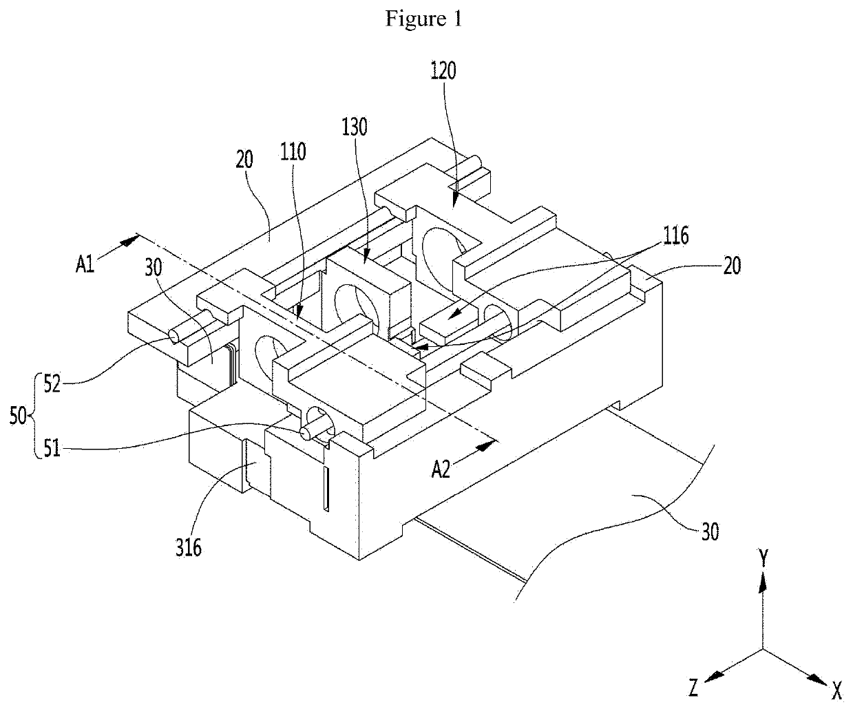
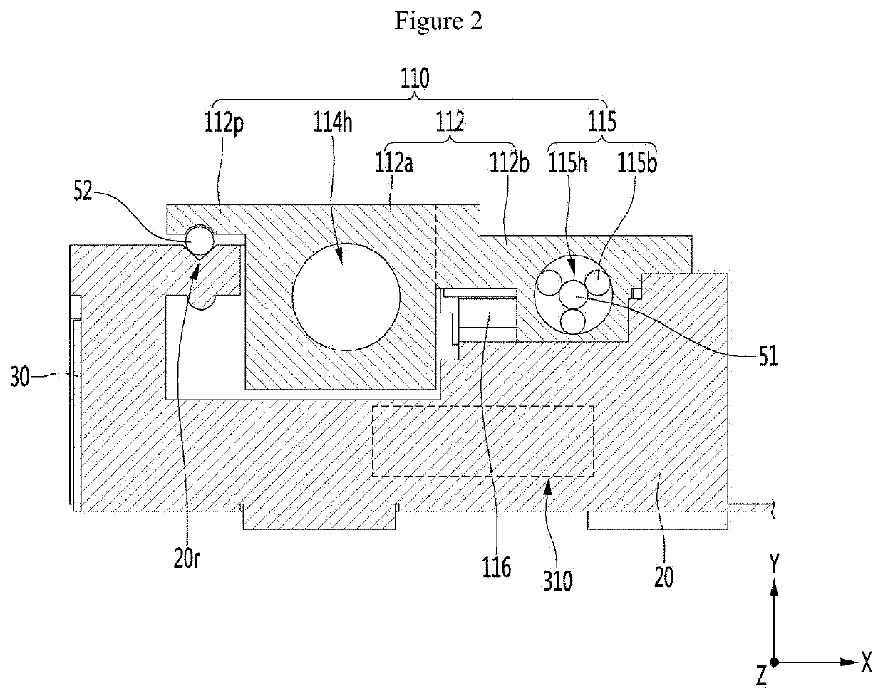
[0053]FIG. 1 is a perspective view of a lens driving device according to an embodiment, and FIG. 2 is a cross-sectional view taken along line A1-A1′ of the lens driving device according to the embodiment shown in FIG. 1.

[0054]In the xyz axis direction shown in FIGS. 1 and 2, the xz plane may represent the ground, the z axis means the optical axis direction or parallel thereto, and the x axis is perpendicular to the z axis in the ground (xz plane). Also, the y-axis may mean a direction perpendicular to the ground.

[0055]In the following description of the embodiment, two moving lens groups are described, but the present invention is not limited thereto. The moving lens group may be three, four, or five or more. In addition, the optical axis direction z may mean a direction that is the same as or parallel to the direction in which the lens groups are aligned.

[0056]First, referring to FIG. 1, in the camera module 100 according to the embodiment, various optical systems may be disposed o...


PUM


Abstract

One embodiment relates to a lens driving device and a camera module including same. The lens driving device according to the one embodiment can include: a base; a pin coupled to the base; and a housing including a lens group and moving in the optical axis direction along the pin. The housing can include, in one side thereof, a ball accommodation part and a plurality of balls arranged in the ball accommodation part. The pin is arranged in the ball accommodation part so as to be capable of guiding the housing while being in contact with the plurality of balls.

Description

TECHNICAL FIELD[0001]Embodiments relate to a lens driving device and a camera module including the same.BACKGROUND ART[0002]The camera module captures a subject and stores it as an image or a video. The camera module is mounted on a mobile terminal such as a mobile phone, a laptop, a drone, or a vehicle.[0003]On the other hand, portable devices such as smartphones, tablet PCs, and laptops have a small camera module, and the camera module has an autofocus function that aligns the focal length of the lens by automatically adjusting the distance between the image sensor and the lens.[0004]Recently, the camera module can perform zooming by zooming in or zooming out of a remote object through a zoom lens. The demand for high magnification zooming more than twice that of camera modules is increasing.[0005]On the other hand, friction torque is generated when the lens is moved by a mechanical movement using a lens driving device for a zooming function in the camera module. Technical problem...

Claims


Application Information

Patent Timeline
Patent Type & Authority Applications(United States)
IPC IPC(8): G02B7/09G03B5/00
CPCG02B7/09G03B2205/0046G03B5/00G03B5/04G03B2205/0069G03B30/00H04N23/00G03B17/12H04N23/55G02B7/10
Inventor CHOI, HYUN HO
Owner LG INNOTEK CO LTD
Why Eureka
Try Eureka