Lens with optical area to increase defocus image area

Pending Publication Date: 2021-04-08
BRIGHTEN OPTIX CORP
View PDF0 Cites 0 Cited by
  • Summary
  • Abstract
  • Description
  • Claims
  • Application Information

AI Technical Summary

Benefits of technology

[0008]The primary objective of the present invention is that the myopia control lens includes a central optical zone and peripheral optical zones surrounding the central optical zone. The central optical zone includes a non-circular optical area, and a defocus area formed on a part thereof other than the optical area. Varies regions of asymmetric periphery optical zones create different amounts of blur surrounding a central imaging area. The outer peripheral surface consists of different regions and different amounts of asymmetrical aspheric, so that the central optical zone can increase a defocus image area of the retina of the eyeball and light passing the peripheral optical zones can create different amounts of peripheral blurring areas in front of different areas of a retina; this defocusing of the images, providing more controlled amount of myopic defocus to the retina, which acts as a putative cue to slow myopic eye growth. Following animal studies that have demonstrated the strong inhibitory effect of peripheral myopic defocus on axial elongation or myopia de

Problems solved by technology

Mobile phone overuse can also lead to vision impairment.
Therefore, what is needed is to develop myopia control lens to solve the problem that the conventional lens is unable to achi

Method used


Image

  • Lens with optical area to increase defocus image area
  • Lens with optical area to increase defocus image area
  • Lens with optical area to increase defocus image area

Examples


Embodiment Construction

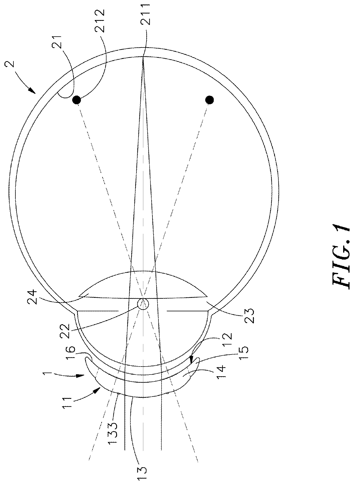
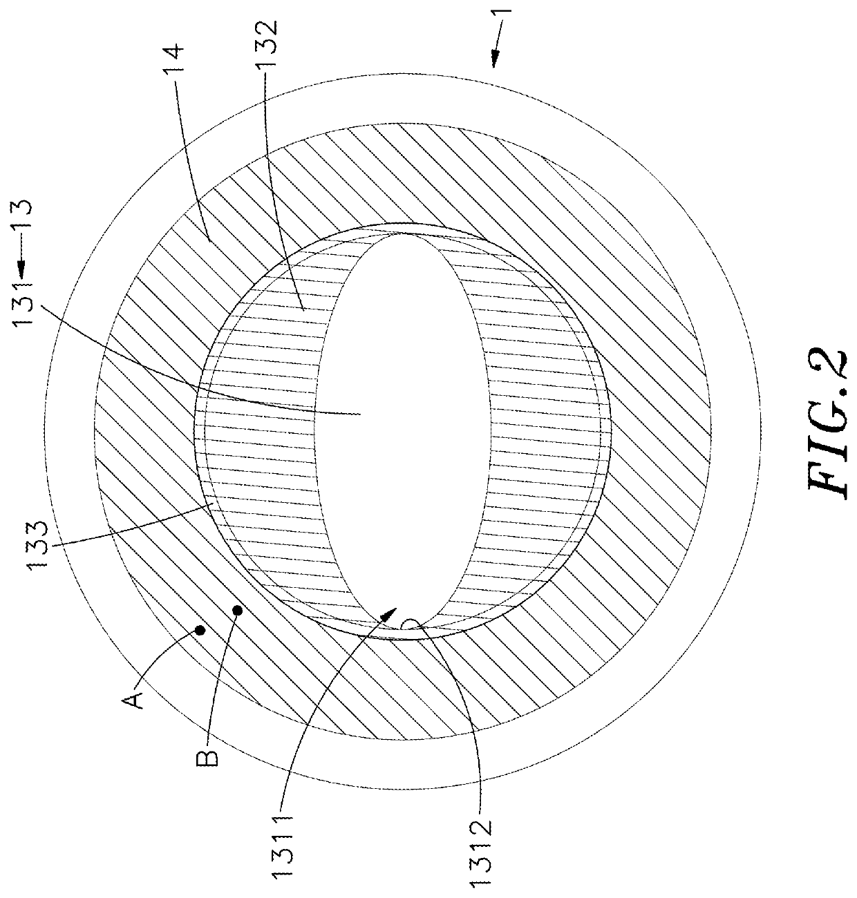
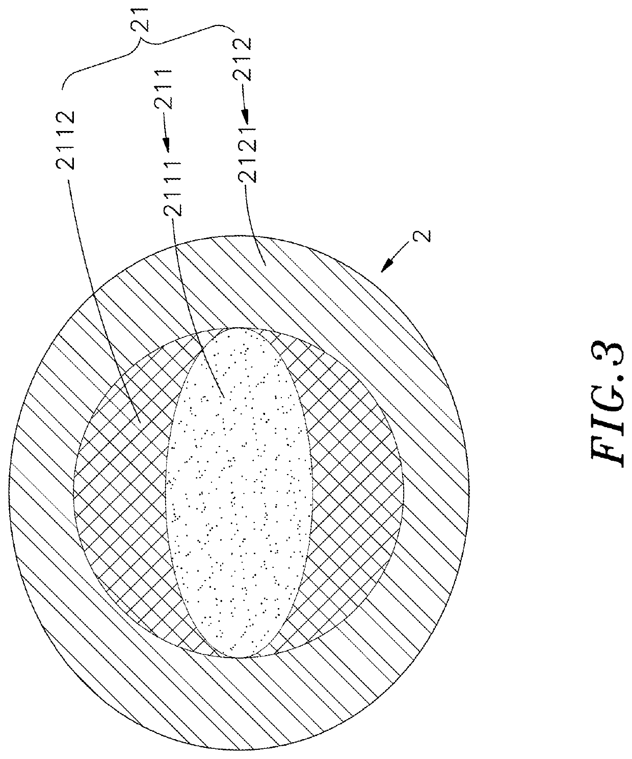
[0014]The following embodiments of the present invention are herein described in detail with reference to the accompanying drawings. These drawings show specific examples of the embodiments of the present invention. These embodiments are provided so that this disclosure will be thorough and complete, and will fully convey the scope of the invention to those skilled in the art. It is to be acknowledged that these embodiments are exemplary implementations and are not to be construed as limiting the scope of the present invention in any way. Further modifications to the disclosed embodiments, as well as other embodiments, are also included within the scope of the appended claims. These embodiments are provided so that this disclosure is thorough and complete, and fully conveys the inventive concept to those skilled in the art. Regarding the drawings, the relative proportions and ratios of elements in the drawings may be exaggerated or diminished in size for the sake of clarity and conv...


PUM


Abstract

A lens with an optical area to increase a defocus image refractive powers is disclosed. A central optical zone of the lens includes a non-circular optical area, and a defocus area formed on a part thereof other than the optical area. An outer surface of the peripheral optical zone is aspheric, so that the original space of the central optical zone can be effectively used to increase the defocus image area of the retina of eye ball and light passing the peripheral optical zones can create different amounts of peripheral blurring areas in front of different areas of the retina; this defocusing of the images, providing more controlled amount of myopic defocus to the retina, which acts as a putative cue to slow myopic eye growth.

Description

[0001]This application is a Continuation-In-Part of application Ser. No. 16 / 158,833, filed on Oct. 12, 2018, for which priority is claimed under 35 U.S.C § 120, the entire contents of which are hereby incorporated by reference.[0002]This application claims the priority benefit of Taiwan patent application number 106217150, filed on Nov. 17, 2017.BACKGROUND OF THE INVENTION1. Field of the Invention[0003]The present invention relates to a lens with an optical area to increase a defocus image area. More particularly, a central optical zone of the lens includes a non-circular optical area, and a defocus area formed on a part thereof other than the optical area, and an outer surface of a peripheral optical zone of the lens is aspheric, so that the original space of the central optical zone can be effectively used to increase the defocus image area of the retina of eye ball, and the aspheric outer surface is used to effectively control myopia progression, thereby slowing or retarding myop...

Claims


Application Information

Patent Timeline
IPC IPC(8): G02C7/04
CPCG02C7/044G02C2202/24G02C7/047G02C7/041
Inventor LIN, WEN-PINCHAN, PING-JUI
Owner BRIGHTEN OPTIX CORP
Why Eureka
Try Eureka