
Vehicle and control method therefor

a control method and vehicle technology, applied in the direction of electrical control, machine/engine, exhaust treatment electric control, etc., can solve the problems of insufficient temperature increase of the catalyst device, inability to send oxygen to the catalyst device, etc., to reduce the deterioration of the drivability of the vehicle and the degradation of the durability of the internal combustion engine

Active Publication Date: 2021-04-15
TOYOTA JIDOSHA KK
View PDF0 Cites 5 Cited by
  • Summary
  • Abstract
  • Description
  • Claims
  • Application Information

AI Technical Summary

Benefits of technology

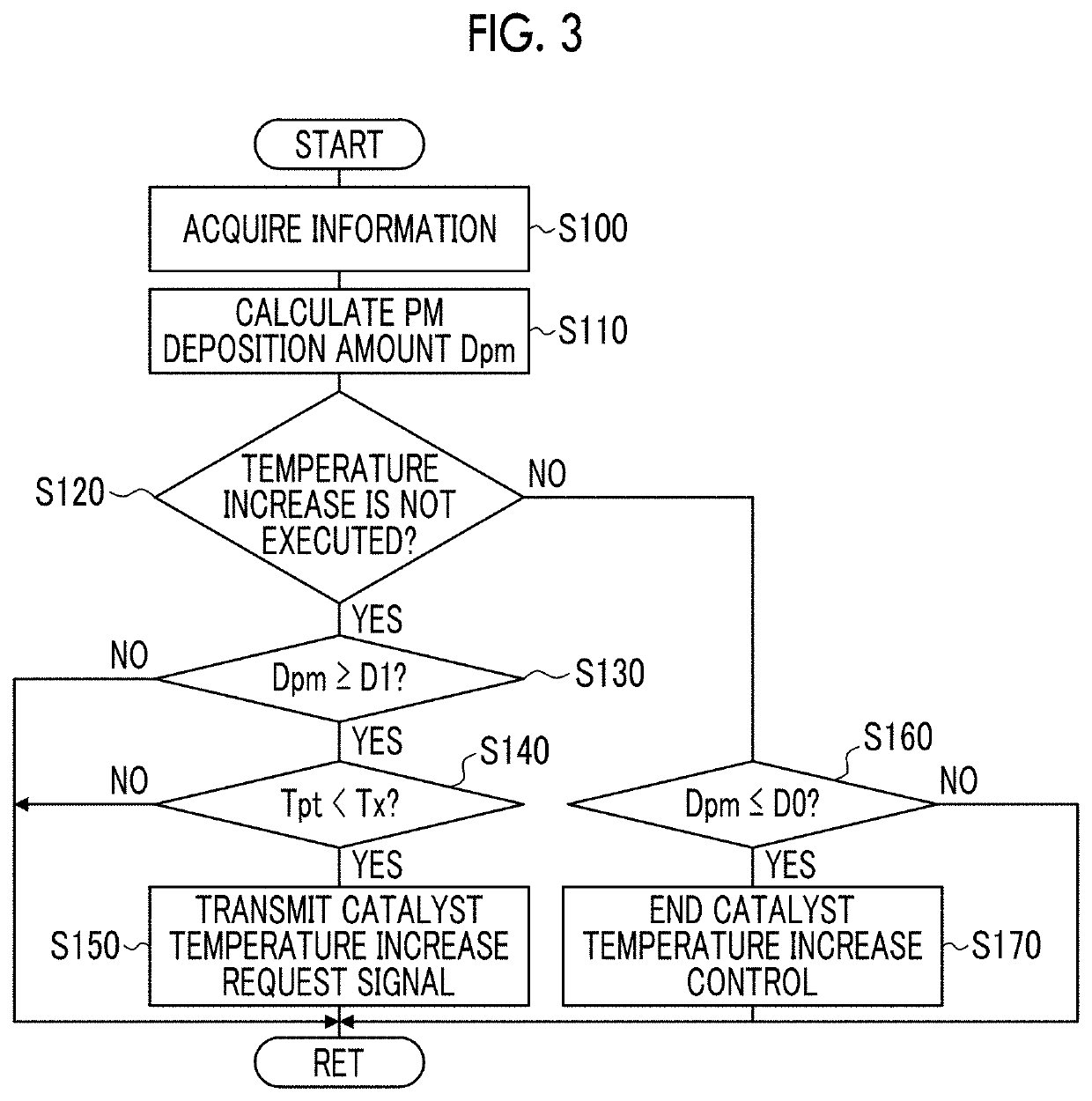
The patent provides a solution to the problem of insufficient air supply to the catalyst device when the environmental temperature is low or the requested temperature is high during catalyst temperature increase control. It also aims to suppress deterioration of vehicle livability and engine durability during load operations. The solution involves a technique for sufficient catalyst temperature increase and oxygen supply to the exhaust gas control apparatus.

Problems solved by technology

However, even though the catalyst temperature increase control of the related art described above is executed, in a case where an environmental temperature is low or in a case where a requested temperature to the catalyst temperature increase control is high, sufficient air, that is, oxygen may not be sent to the catalyst device and the catalyst device may not be sufficiently increased in temperature.

Method used


Image

  • Vehicle and control method therefor
  • Vehicle and control method therefor
  • Vehicle and control method therefor

Examples


Embodiment Construction

[0029]Next, a mode for carrying out the present disclosure will be described referring to the drawings.

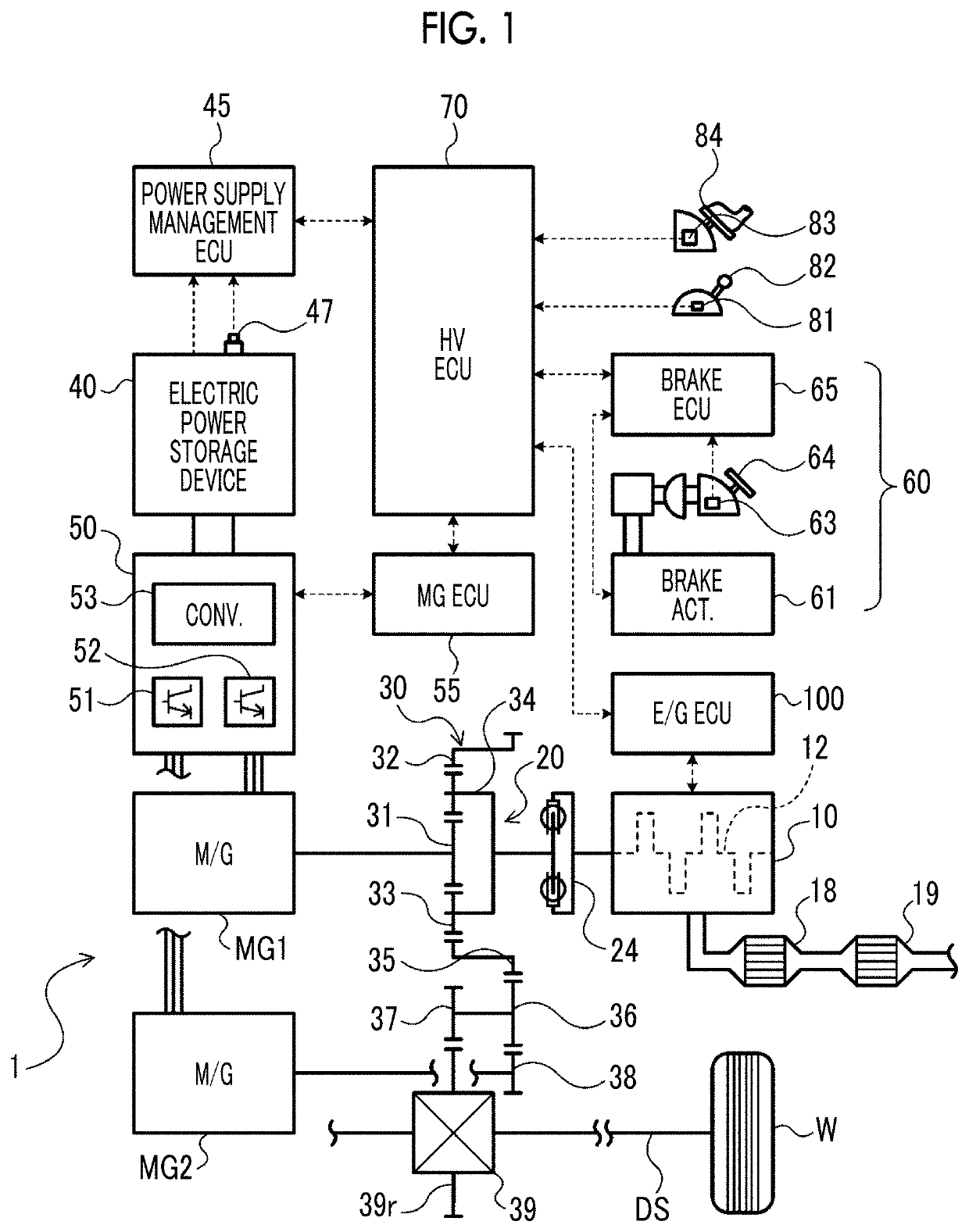
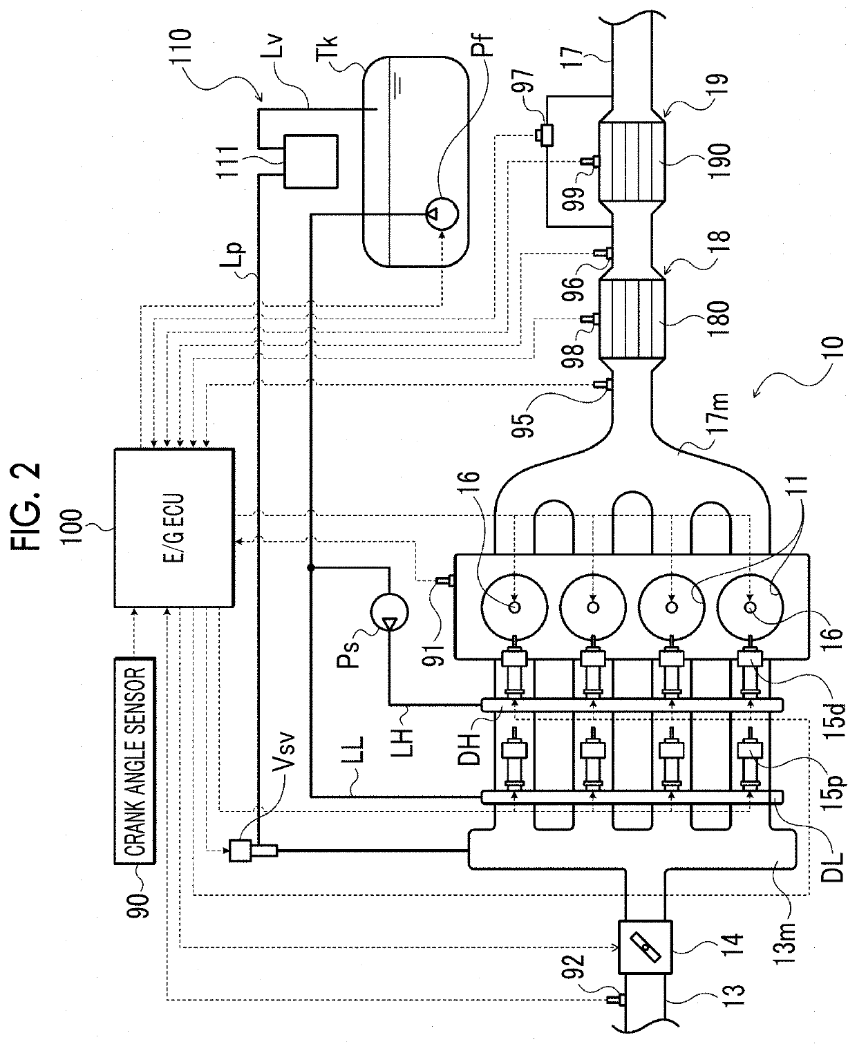
[0030]FIG. 1 is a schematic configuration diagram showing a hybrid vehicle 1 that is a vehicle of the present disclosure. The hybrid vehicle 1 shown in the drawing includes multi-cylinder engine (hereinafter, simply referred to as an “engine”) 10 including a plurality (in the embodiment, for example, four) of cylinders (combustion chamber) 11, a single-pinion type planetary gear 30, motor generators MG1, MG2, both of which are synchronous motor generators (three-phase alternating-current electric motors), an electric power storage device (battery) 40, an electric power control unit (hereinafter, referred to as “PCU”) 50 that is connected to the electric power storage device 40 and drives the motor generators MG1, MG2, an electronically controlled hydraulic braking device 60 that is able to provide frictional braking force to wheels W, and a hybrid electronic control unit (hereinaft...


PUM


Abstract

A vehicle includes a power generation device including a multi-cylinder engine, the power generation device being configured to output drive power to wheels, an exhaust gas control apparatus including a catalyst for removing exhaust gas from the multi-cylinder engine, and a control device configured to execute catalyst temperature increase control for stopping fuel supply to at least one cylinder and supplying fuel to remaining cylinders in a case where a temperature increase of the catalyst is requested during a load operation of the multi-cylinder engine, execute control such that the power generation device supplements insufficient drive power due to the execution of the catalyst temperature increase control, and change the cylinder, to which the fuel supply is stopped, according to a stop frequency of the fuel supply or an elapsed time from a start of the stop of the fuel supply during the execution of the catalyst temperature increase control.

Description

INCORPORATION BY REFERENCE[0001]The disclosure of Japanese Patent Application No. 2019-186127 filed on Oct. 9, 2019 including the specification, drawings and abstract is incorporated herein by reference in its entirety.BACKGROUND1. Technical Field[0002]The present disclosure relates to a vehicle including a multi-cylinder engine and an exhaust gas control apparatus including a catalyst for removing exhaust gas from the multi-cylinder engine, and a control method therefor.2. Description of Related Art[0003]In the related art, a control device that, in a case where an SOx poisoning amount of a catalyst device disposed in an exhaust passage of an internal combustion engine exceeds a predetermined value, executes catalyst temperature increase control (dither control) for setting an air-fuel ratio of a part of cylinders (rich cylinders) to rich and setting an air-fuel ratio of a part of cylinders (lean cylinders) to lean is known (for example, see Japanese Unexamined Patent Application P...

Claims


Application Information

Patent Timeline
Patent Type & Authority Applications(United States)
IPC IPC(8): F02D41/02F02B75/22F01N3/10F02D41/38
CPCF02D41/025F02B75/22F02D2200/101F02D41/38F01N3/10F02D41/024F02D41/029F02D41/003F02D41/3094F02D29/02F01N2430/06F01N9/00F01N11/00F01N3/20F01N2560/06F01N2900/1602F02D41/0087
Inventor NOSE, YUKIKOBAYASHI, MASAAKI
Owner TOYOTA JIDOSHA KK
Learn More