Conveyance device, driven unit, auxiliary unit, and pallet
a technology of conveying device and pallet, which is applied in the direction of mechanical conveyors, packaging, metal working devices, etc., can solve the problems of cost increase and cost increase, and achieve the effect of suppressing the manufacturing cost of pall
- Summary
- Abstract
- Description
- Claims
- Application Information
AI Technical Summary
Benefits of technology
Problems solved by technology
Method used
Image
Examples
first embodiment
[0027]
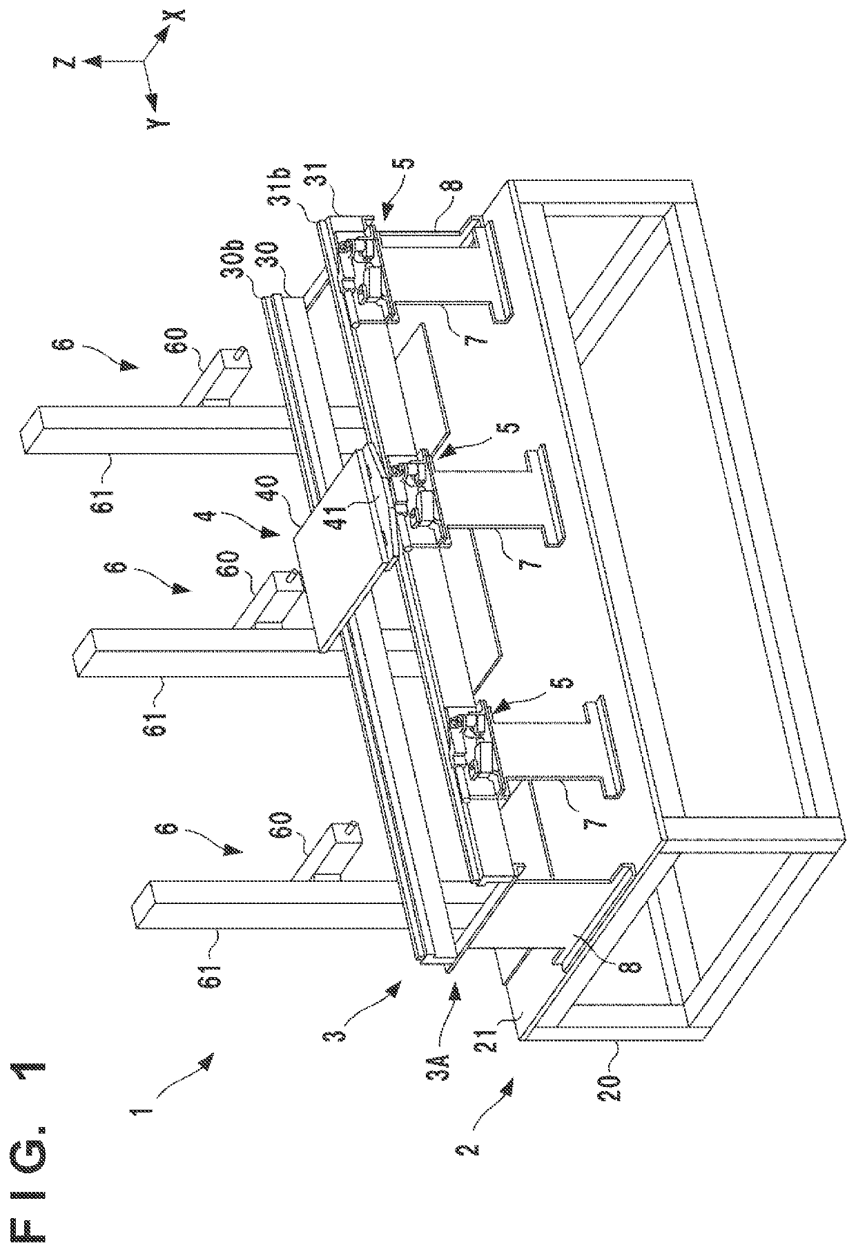
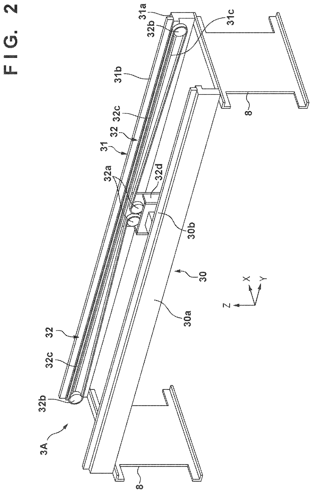
[0028]FIG. 1 is a perspective view of a work system 1 to which the present invention is applied. The work system 1 includes a stand 2, a conveyance device 3 that conveys a workpiece (not shown), and a plurality of work devices 6. The conveyance device 3 includes a plurality of stopping units 5. In an actual factory or the like, the work system is constructed by forming a conveyance layout using a plurality of the conveyance devices 3 based on the workpiece conveyance specifications, and appropriately arranging each work device 6 at a predetermined position in the formed conveyance layout. For example, as in a layout example shown in FIG. 18, a configuration can be constructed in which a plurality of the stands 2 and the conveyance devices 3 shown in FIG. 1 (two stands and two conveyance devices in the example shown in FIG. 18) are arranged in the Y direction.
[0029]The stand 2 is a structure that supports the conveyance device 3 and the plurality of work devices 6. The stand 2 ...
second embodiment
[0095]Detecting that the pallet 4 has reached the stop position can provide a guide for a timing of starting work on a workpiece by the work device 6. Therefore, a sensor for detecting that the pallet 4 has reached the stop position may be provided. In this case as well, by arranging a sensor on the support frame 31 and providing the driven unit 41 with a detection target portion to be detected by the sensor, alignment and the like upon changing specifications become easy.
[0096]FIG. 15 is a perspective view showing an example of a driven unit 41 provided with a detection target portion 412. In the example shown in FIG. 15, the detection target portion 412 is fixed to the inner side surface of a main body member 41a. FIG. 16 is a sectional view showing an arrangement example of a sensor 9 that detects the detection target portion 412. The sensor 9 is, for example, an optical sensor or a magnetic sensor, and detects whether the detection target portion 412 exists immediately above it....
third embodiment
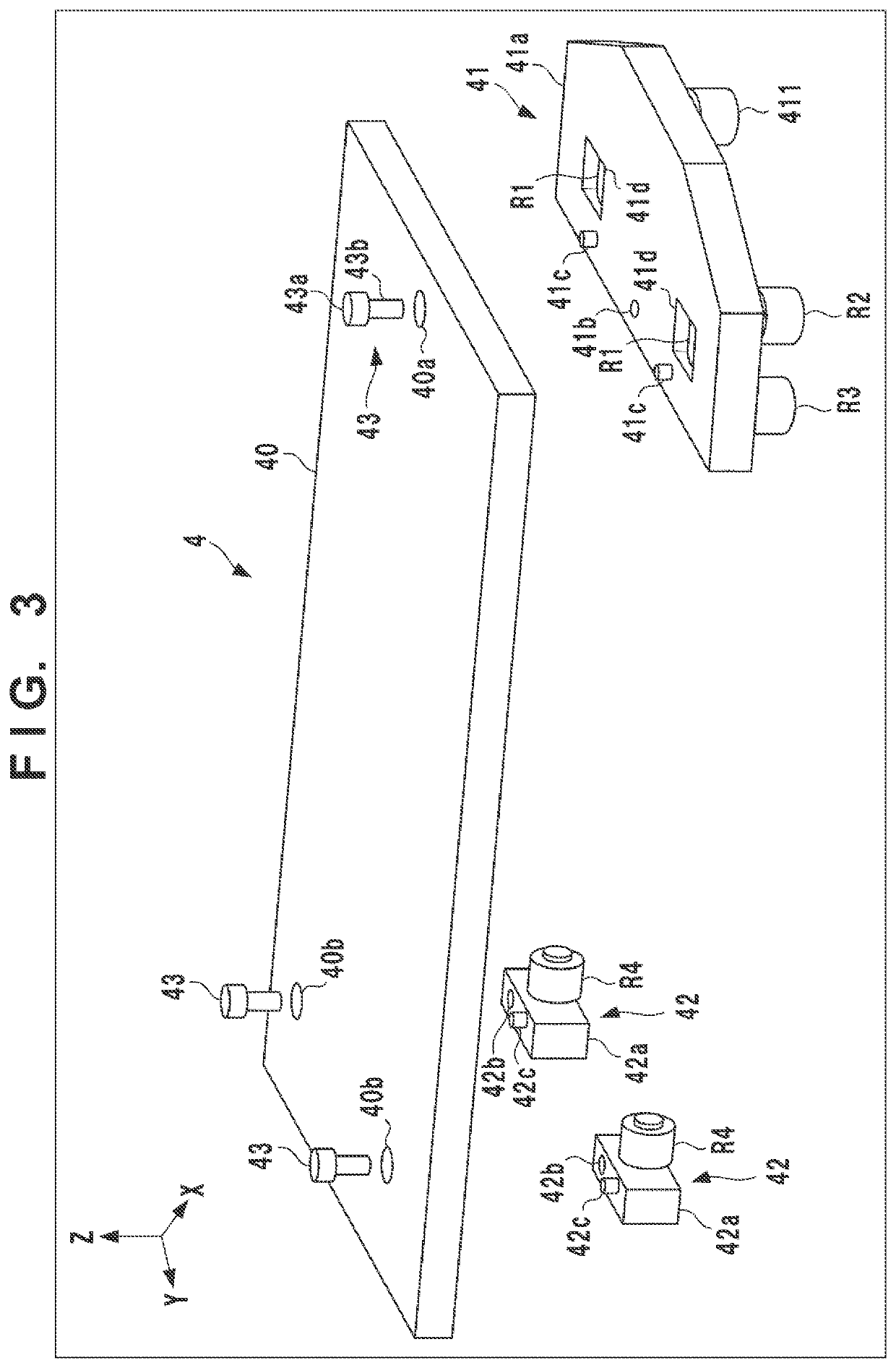
[0098]The numbers and positions of the driven units 41 and the auxiliary units 42 in the pallet 4 can be appropriately selected. FIG. 17 shows another arrangement example of the pallet 4. The shown example is an arrangement example of a pallet 4 suitable for a relatively large workpiece. Six auxiliary units 42 are provided. Two of them are arranged at the front and back of a driven unit 41 and configured to travel on the support frame 31 (not shown in FIG. 17). Remaining four auxiliary units 42 are configured to travel on the support frame 30 (not shown in FIG. 17). When it is necessary to change the specifications of the pallet 4 since the type of workpiece is changed, it is possible to change the specifications as described above. In this case as well, it is not required to redesign the driven unit 41 and the auxiliary unit 42, and only a placement member 40 may be newly designed.
PUM
 Abstract
Description
Claims
Application Information
 - R&D
- Intellectual Property
- Life Sciences
- Materials
- Tech Scout
- Unparalleled Data Quality
- Higher Quality Content
- 60% Fewer Hallucinations
Browse by: Latest US Patents, China's latest patents, Technical Efficacy Thesaurus, Application Domain, Technology Topic, Popular Technical Reports.
© 2025 PatSnap. All rights reserved.Legal|Privacy policy|Modern Slavery Act Transparency Statement|Sitemap|About US| Contact US: help@patsnap.com


