Fence frame and fence system

a fence system and frame technology, applied in the field of fence frame and fence system, can solve the problems of wasting time and labor, facilitating subsequent reuse, and inability to achieve the ideal protection effect, and achieve the effect of reducing device investment, simple operation, and convenient us

Active Publication Date: 2021-04-22
HEFEI WISDOM BRIDGE INFORMATION TECH CO LTD
View PDF0 Cites 2 Cited by
  • Summary
  • Abstract
  • Description
  • Claims
  • Application Information

AI Technical Summary

Benefits of technology

[0027]1. In the fence frame of the present invention, by changing the position state of the wheel bodies, the fence frame has double functions of a transport device and the fence system component and is simple in operation and convenient to use, so that the fence system needs no transfer equipment in the transfer process, thereby reducing the device investment and achieving good economical performance and good practicability.
[0028]2. The fence system of the present invention adopts an assembling mode in which a plurality of assembly units are connected by the buckles, thereby realizing convenience in assembling and disassembling and greatly increasing the working efficiency for constructing the protective net.
[0029]3. The fence assembly units of the ...

Problems solved by technology

Although the above structure has certain warning effect, there are a lot of disadvantages in an actual application process because of structural and design limitations.
Firstly, by adopting the connection way such as hanging, rope fastening and the like, the protective net is infirm in connection and difficult to fix, and is easy to loosen and drop off, so that an ideal protection effect cannot be achieved.
Secondly, when the vertical bars and the protective net are disassembled after used, the operation is complicated, thereby wasting time and labor; and moreover, the protective net and the vertical bars are stacked and transferred after separated, which is easy to cause the problems such as intertwining and local knotting of the protective ne...

Method used


Image

  • Fence frame and fence system
  • Fence frame and fence system
  • Fence frame and fence system

Examples


Embodiment Construction

[0047]Preferred embodiments of the present invention are described in detail below in conjunction with the drawings to make the advantages and features of the present invention more easily understood by those skilled in the art, so as to define the protection scope of the present invention more clearly.

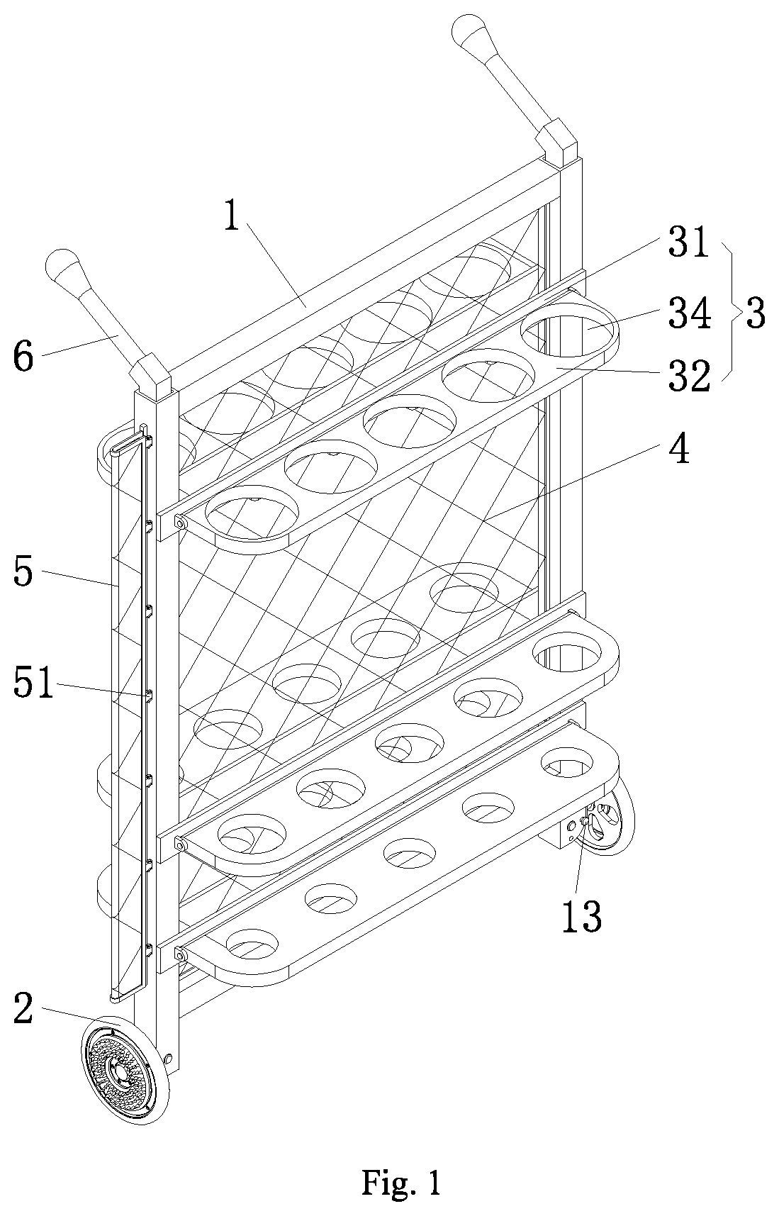
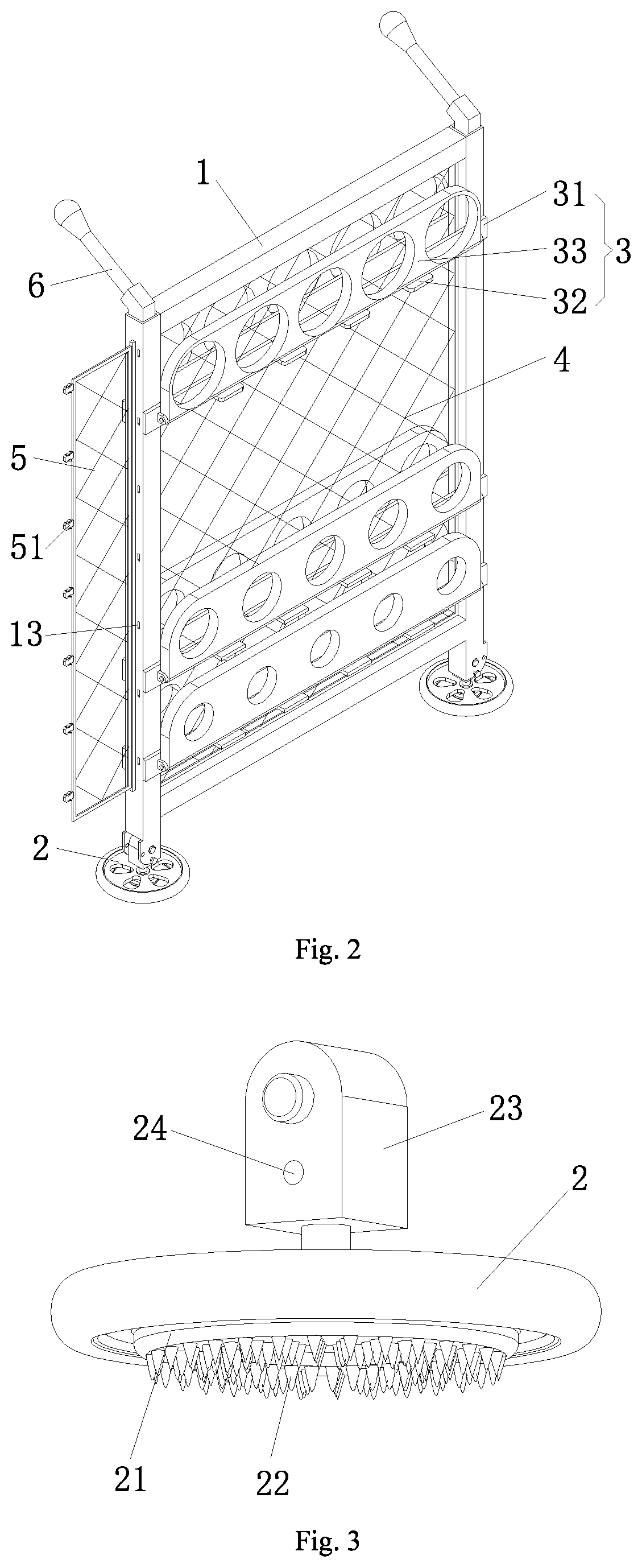
[0048]Referring to FIG. 1 and FIG. 2, a fence frame includes a framework 1, wheel bodies 2 rotatably connected to two sides of the bottom of the framework 1, and storage racks 3 movably arranged on the end surface of the framework 1. The framework 1 is of a square framework structure formed by connecting square profile steel or bolts.

[0049]The storage racks 3 are arranged symmetrically on two end surfaces of the framework 1. Each end surface is provided with an upper layer, middle layer and lower layer of storage racks 3. Each of the storage racks 3 includes a crossbeam plate 31 fixed on the end surface of the framework 1 and a storage plate 32 rotatably connected to the outer side su...


PUM


Abstract

Disclosed a fence frame and a fence system. The fence frame includes a framework, wheel bodies rotatably connected to two sides of the bottom of the framework, and a plurality of storage racks movably arranged on the end surface of the framework. A fixed net is arranged in the framework, and one side wall of the framework is provided with a connecting net. The wheel bodies can be horizontally/vertically fixed on the bottom of the framework. The fence system is mainly composed of the above fence frame and a plurality of fence assembly units arranged on the fence frame. The fence assembly units are detachably connected with the fence frame in sequence. The fence frame of the present invention realizes convenience in disassembling and assembling, facilitates the transfer and reuse of the assembly units; and enhances the stability of the assembly units and the overall structure.

Description

CROSS-REFERENCE TO RELATED APPLICATIONS[0001]This application is a continuation of International Patent Application No. PCT / CN2019 / 109777, filed on Sep. 30, 2019. The content of the aforementioned applications, including any intervening amendments thereto, is incorporated herein by reference in its entirety.TECHNICAL FIELD[0002]The present invention relates to the technical field of electric power construction equipment, and particularly relates to a fence frame and a fence system.BACKGROUND OF THE PRESENT INVENTION[0003]At present, in order to meet the safety requirement in the construction or maintenance process of electric power, protective fences must be erected on construction sites so as to effectively prevent non-construction personnel from entering the construction or maintenance site of the electric power.[0004]The existing electric power protective fence is generally composed of a left vertical bar, a right vertical bar and a protective mechanism (generally a protective ne...

Claims


Application Information

Patent Timeline
IPC IPC(8): E04H17/06E04H17/10
CPCE04H17/06E04H17/124E04H17/14E04H17/20E04H17/22B62B1/12B62B5/00B65H75/40B65H75/44B62B2202/025E04H17/08
Inventor LI, RUOMEISHI, KAN
Owner HEFEI WISDOM BRIDGE INFORMATION TECH CO LTD
Why Eureka
Try Eureka