Reduced power operation of a wind turbine

Active Publication Date: 2021-04-22
WOBBEN PROPERTIES GMBH
View PDF0 Cites 1 Cited by
  • Summary
  • Abstract
  • Description
  • Claims
  • Application Information

AI Technical Summary

Benefits of technology

The patent text describes a method to reduce stress and noise emissions from wind power installations. By increasing the rotor rotation speed and avoiding torsional oscillations, stalling on the rotor blades can be avoided, reducing the stress on the wind installation. The method proposes two variations in how the rotation speed is increased, depending on the wind speed and the stress on the blades. In the reduced operating mode, the rotation speed is initially increased to a level that prevents stalling, and then maintained at a higher level to reduce stress. The increased rotation speed also helps to counteract any torsional oscillations that may occur. Overall, this method improves the performance and efficiency of wind power installations.

Problems solved by technology

While the same operating point does result from the point of view of the generator, it has however been found that this artificial reduction has the consequence that reduced power operating modes always have significantly lower rated rotation speeds than the power-optimized mode.
It has been recognized that at high wind speeds and the corresponding blade angles such low tip speed ratios can lead to stalling on the rear side of the rotor blade profile.
It can be particularly problematic here that such stalls only occur at a few positions along the full length of the rotor blade.
This can in turn lead to increased torsion stresses.
Because such stalls only occur in partial regions, the wind power installation continues however to be driven by the wind, so that the aerodynamic rotor continues to turn and continues to be exposed to stresses.
The problem of low tip speed ratios at high wind speeds occurs in particular at the transition region to storm operation.

Method used


Image

  • Reduced power operation of a wind turbine
  • Reduced power operation of a wind turbine
  • Reduced power operation of a wind turbine

Examples


Embodiment Construction

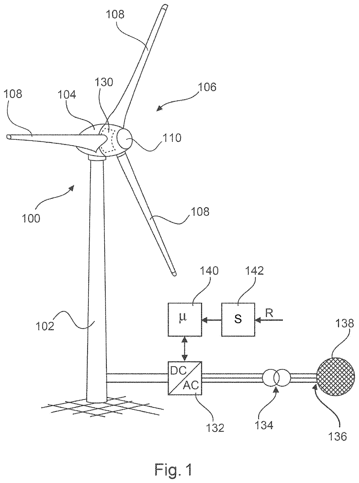
[0075]FIG. 1 shows a wind power installation 100 with a tower 102 and a nacelle 104. A rotor 106 with three rotor blades 108 and a spinner 110 is arranged at the nacelle 104. The rotor 106 when operating is set into rotary movement by the wind, thereby driving a generator in the nacelle 104.

[0076]In FIG. 1, a generator 130 that generates electric power and transfers it to an inverter 132 is moreover indicated in the nacelle 104, wherein alternating current previously generated by the generator was rectified. The inverter 132 feeds into the electrical supply grid 138 via a transformer 134 at a grid connection point 136.

[0077]A control apparatus (controller) 140 that operates the inverter 132, which forms a feed apparatus, is provided for control of the inverter 132. For a reduced-power operating mode, a reduction signal R can be supplied to a switching apparatus (processor, computer or controller) 142. The switching apparatus 142, which can also be part of the control apparatus 140, ...


PUM


Abstract

A method for operating a wind power installation is provided. The wind power installation comprises an aerodynamic rotor with rotor blades, where the rotor can be operated with a variable rotor rotation speed. The wind power installation outputs an output power generated from wind for feeding into an electrical supply grid. The wind power installation can be operated in a normal operating mode without power reduction and in a reduced operating mode with power reduction, in which a specified power reduced with respect to a rated installation power is specified. When operating in the reduced operating mode for wind speeds above a rated wind speed, at least in one rotation speed increase region, the wind power installation increases its rotor rotation speed as the wind speed rises further.

Description

BACKGROUNDTechnical Field[0001]The present invention relates to a method for operating a wind power installation. The present invention also relates to a wind power installation.Description of the Related Art[0002]Wind power installations are known, and they generate electric power from wind and usually feed this electric power into an electrical supply grid that is regularly maintained by network operators. Wind power installations are ideally operated in what is known as parallel grid operation in which each wind power installation generates as much power, feeding it into the electrical supply grid, as is possible on the basis of the prevailing wind, giving consideration to technical limits of the wind power installation concerned.[0003]With the increasing number of wind power installations in the electrical supply grid, their influence on the behavior of the electrical supply grid also grows, and in some circumstances can also affect the stability of the electrical supply grid. F...

Claims


Application Information

Patent Timeline
IPC IPC(8): F03D7/02F03D9/25F03D7/04H02J3/38H02J3/46
CPCF03D7/0284F03D7/0276F03D9/25F03D7/048H02J2300/28H02J3/46F05B2270/3201F05B2270/1033F05B2220/706H02J3/381Y02E10/72Y02E10/76F05B2270/1077
Inventor MESSING, RALFMÖLLER, CHRISTIAN
Owner WOBBEN PROPERTIES GMBH
Why Eureka
Try Eureka