Method for producing a blinker module, blinker module, rear-view device, and motor vehicle

a technology of rear-view device and blinker, which is applied in the direction of instrument, lighting and heating apparatus, planar/plate-like light guide, etc. it can solve the problems of division of blinker, no longer arranged on the table, and loss of light to the lighting element, and achieves simple and inexpensive manufacturing, easy assembly, and great freedom in the design of individual elements.

Active Publication Date: 2021-04-22
MOTHERSON INNOVATIONS CO LTD
View PDF0 Cites 0 Cited by
  • Summary
  • Abstract
  • Description
  • Claims
  • Application Information

AI Technical Summary

Benefits of technology

The invention is a blinker module that is easy to manufacture, handle, and design. It is made up of two layers, one of which acts as a reflector layer to provide even illumination and prevent light loss. The second layer acts as a cover and can be designed to fit different housing configurations. This allows for easy installation and flexibility in design. Both layers can be manufactured separately, making it cost-effective to produce small numbers of blinker modules. The interaction between the two layers is effective, creating separate lighting regions that can be optimized for different designs. Overall, the invention provides a simple yet efficient solution for creating blinker modules.

Problems solved by technology

In both cases the light would be lost to the lighting element.
In addition, this also results in a division of the blinker module into two effective light regions.
However, when the glass hovers over the coaster, it is no longer arranged on the table in the sense of the terminology of this disclosure.

Method used


Image

  • Method for producing a blinker module, blinker module, rear-view device, and motor vehicle
  • Method for producing a blinker module, blinker module, rear-view device, and motor vehicle
  • Method for producing a blinker module, blinker module, rear-view device, and motor vehicle

Examples


first embodiment

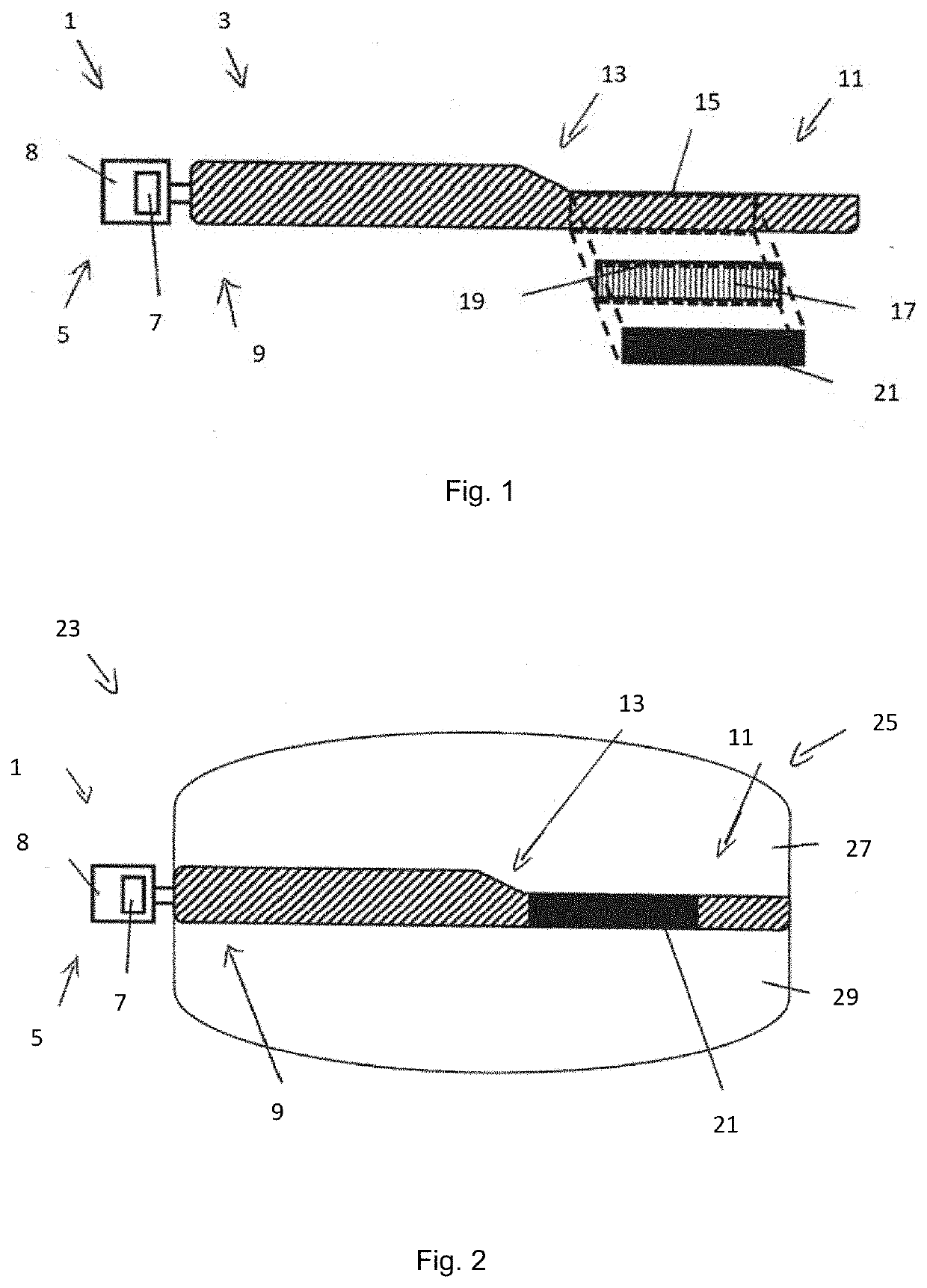
[0068]FIG. 1 shows a blinker module 1 according to the disclosure, in a partial exploded representation.

[0069]The blinker module 1 comprises a lighting element 3, which has a light guide with a light disk that is an integral part of it. The blinker module 1 further comprises a illuminant unit 5, which has at least one illuminant 7, for example in the form of an LED, which is arranged on a circuit board 8. The light emitted by the illuminant unit 5 is coupled into the light guide at a first end 9 of the lighting element 3 and then propagates in the light guide. By means of the light disk, a planar illumination impression along the light guide is achieved. The schematic view in FIG. 1 is shown from the direction of oncoming traffic. The lighting element 3 has a flat front part (in FIG. 1 in the drawing plane). However, any other surface shapes are also possible.

[0070]In an end section 11 of the lighting element 3, which is opposite the first end 9, the lighting element 3 tapers in the...

third embodiment

[0086]FIGS. 8a and 8b show a blinker module, being an alternative to the blinker module 50 and similar parts are provided with the same reference number hyphenated.

[0087]Turning now to FIG. 8a, it can be seen that two illuminants 57′ in form of LEDs are provided on a printed circuit board 58′ in order to emit light into the light guide 53′ provided with a texture 54′ in form of radiator bar optics to enhance homogeneity of the illumination along the path from the illuminants57′ to the opposite end of the light guide 53. The light being reflected within the light guide 53′ is further propagating until said opposite end of the light guide 53′ in order to fulfill the blinker function.

[0088]At the end next to the illuminants 57′ an insert 65′ is arranged between the light guide 53′ and the outer lens 60′. Said insert 65′ is carrying an imprint of the Italian flag on the side facing the outer lens 60′ such that the blinker module 50′ fulfills a further design feature, namely displaying t...


PUM

PropertyMeasurementUnit
shapeaaaaaaaaaa
coloraaaaaaaaaa
colorsaaaaaaaaaa

Abstract

A method for manufacturing a blinker module for a rearview device of a motor vehicle includes the steps of providing at least one lighting element comprising at least one light guide and at least one light disk or lens and providing of at least one illuminant unit comprising at least one illuminant, wherein the illuminant unit is designed to couple light emitted by the illuminant into the lighting element. A blinker module, rearview device and motor vehicle, including the blinker module manufactured according to the method, are also described.

Description

CROSS-REFERENCE TO RELATED APPLICATIONS[0001]This application is a continuation-in-part of International Patent Application No. PCT / EP2019 / 066269, filed Jun. 19, 2019, which claims the benefit of priority to German Patent Application No. DE102018115693.6, filed Jun. 28, 2018, each of which is hereby incorporated by reference in its entirety for all purposes.BACKGROUND1. Field of the Invention[0002]The present disclosure refers to a method for manufacturing a blinker module. The disclosure also relates to a blinker module which can be manufactured or produced by such a method, a rearview device with such a blinker module and a motor vehicle with such a rearview device.2. Related Art[0003]Blinker modules are known from the state of the art in many ways. These are integrated within a housing of the rearview device. More and more often, blinker signals are used which have two spatially separated light regions. The first light region serves primarily as a design feature, which gives the ...

Claims


Application Information

Patent Timeline
Patent Type & Authority Applications(United States)
IPC IPC(8): F21S43/235B29D11/00B60R1/12B60R1/06B60Q1/32B60Q1/00B60Q1/34
CPCF21S43/235B29D11/00692B60R1/1207F21W2103/25B60Q1/32B60Q1/0017B60Q1/34B60R1/06B60Q1/2665G02B6/002G02B6/0055G02B6/0058B29C45/1679B29C45/1643B29C45/1671B29L2011/00B29L2011/0083B29L2031/3055F21S43/14F21S43/237F21S43/245F21S43/247F21S43/26F21S43/33F21S43/40B60Q1/38
Inventor ERHART, VOLKERMEIER, EUGENSCHMIDT, OLIVERRÖTZER, ILKATHOMPSON, ANDREWDICKSON, JAMES
Owner MOTHERSON INNOVATIONS CO LTD
Why Eureka
Try Eureka