
Eye dropper grip with mirror

a dropper and mirror technology, applied in the field of medicine droppers, can solve the problems of difficult positioning or squeezing of the dropper bottle for users, limited solution to only a particular bottle shape and size, and difficulty for users with difficulty with fine motor skills

Inactive Publication Date: 2021-04-29
PRIETO CLARISSA
View PDF0 Cites 1 Cited by
  • Summary
  • Abstract
  • Description
  • Claims
  • Application Information

AI Technical Summary

Benefits of technology

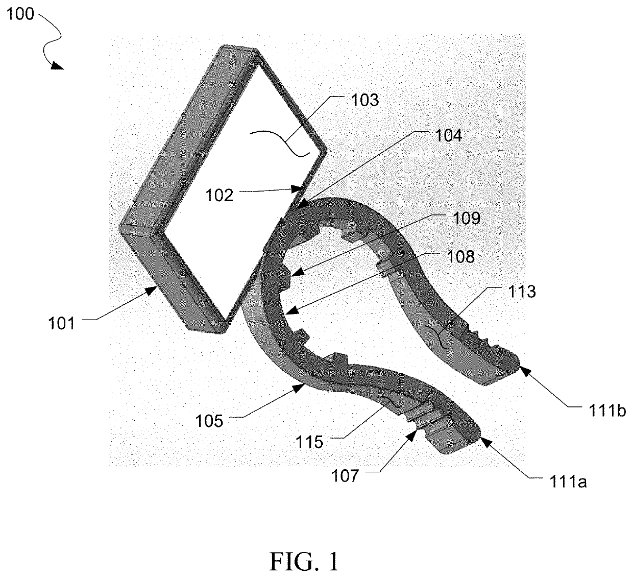
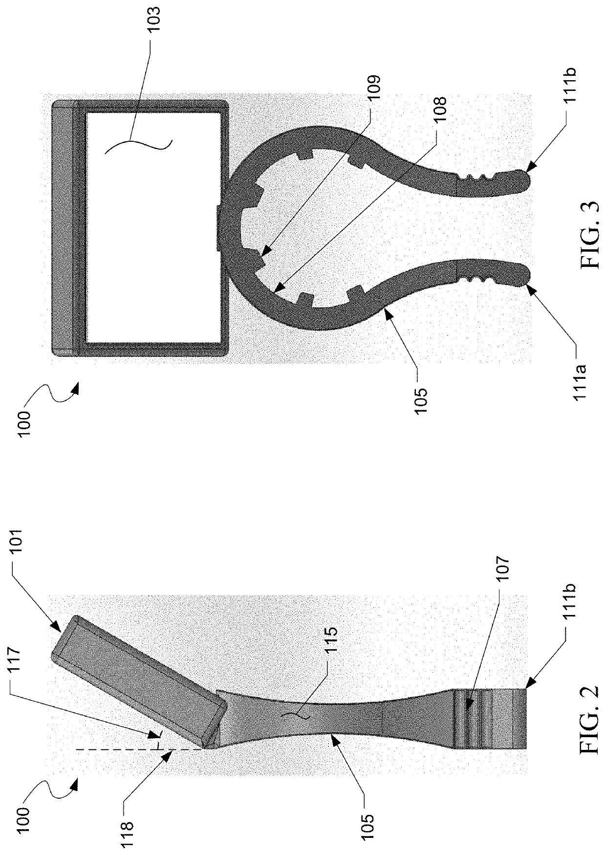
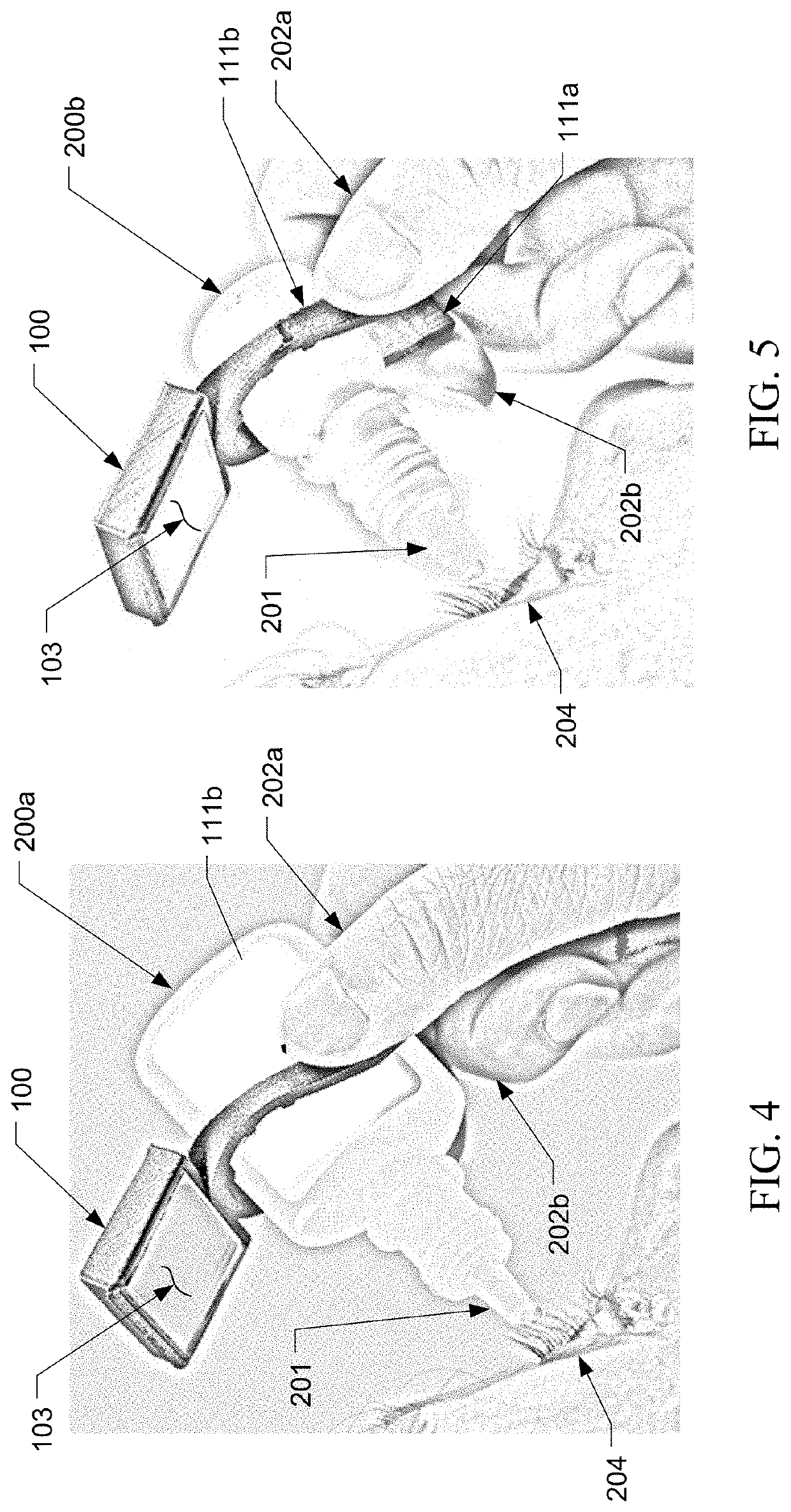
The present patent application is for an eye dropper guide that can be used with different types of dropper bottles. The guide is easy to install and helps the user to squeeze the bottle and release the medication. The guide includes a mirror and a clip that can be attached to the bottle to hold the indicator in place. This clip has prongs that grip the bottle and give the user leverage, so that they only need to apply a small amount of force to compress the dropper. The technical effect of this invention is to provide a versatile and convenient tool for applying eye drops.

Problems solved by technology

Correct positioning of the dropper bottle while applying the medicinal eye drops can be difficult endeavor for a user for a variety of reasons: the user may be inexperienced at applying eye drops, may feel uncomfortable and hesitant about the sensation of dropping liquids into the eye, or may have a fine motor skill disability that makes positioning or squeezing of the dropper bottle difficult for the user.
However, the proposed solutions have several disadvantages.
Some proposed solutions describe a ring mount that couples to the dropper bottle to either the squeezable body of the dropper bottle or the neck portion of the dropper bottle, however, this solution is limited to only a particular bottle shape and size.
Furthermore, the ring mount requires the user to slide the ring mount over an end of the dropper bottle, which may be difficult for users who have difficulty with fine motor skills.
In some instances, the dropper bottle may be difficult to squeeze to expel the medicinal drops for a user that has weakened hand strength.
In this situation, the previously mentioned solutions offer no relief since the ring mount is static and inflexible, i.e., the ring mount does not assist in squeezing the dropper bottle.

Method used


Image

  • Eye dropper grip with mirror
  • Eye dropper grip with mirror
  • Eye dropper grip with mirror

Examples


Embodiment Construction

[0020]Illustrative embodiments of the preferred embodiment are described below. In the interest of clarity, not all features of an actual implementation are described in this specification. It will of course be appreciated that in the development of any such actual embodiment, numerous implementation-specific decisions must be made to achieve the developer's specific goals, such as compliance with system-related and business-related constraints, which will vary from one implementation to another. Moreover, it will be appreciated that such a development effort might be complex and time-consuming but would nevertheless be a routine undertaking for those of ordinary skill in the art having the benefit of this disclosure.

[0021]In the specification, reference may be made to the spatial relationships between various components and to the spatial orientation of various aspects of components as the devices are depicted in the attached drawings. However, as will be recognized by those skille...


PUM


Abstract

The dropper mount assembly includes an angled mirror and a clip that mounts to an eye drop bottle. The angled mirror allows the user to gain proper alignment by viewing a reflection of the expected trajectory of the medicinal eye drop to the eye of the user. The clip is configured to receive eye drop bottles having a circular or oval cross section and is capable of either being mounted from an axis end of the eye drop bottle or from a side of the eye drop bottle. The clip has a set of prongs that provide a number of features, including providing spring tension against the eye dropper bottle, are permitted to receive eye dropper bottles of variable sizes, and serve as a grip and leverage that assists the user in squeezing the eye drop bottle when the user contracts the prongs together.

Description

CROSS REFERENCE TO RELATED APPLICATIONS[0001]This application claims the benefit of an earlier filing date and right of priority to U.S. Provisional Application No. 62925962, filed 25 Oct. 2019, the contents of which is incorporated by reference herein in its entirety.BACKGROUND OF THE INVENTION1. Field of the Invention[0002]The present application relates to medicine droppers, and more particularly to eye droppers equipped with a reflector for guiding placement of eye drops into an eye of a user.2. Description of Related Art[0003]In general, medicinal eye drops are dispensed from a dropper bottle while the dropper bottle is in an inverted position located above an eye of a user such that the eye drops exit from a nozzle of the dropper bottle and fall into the eye of the user while the user is looking up. To dispense the medicinal eye drops, the user gently squeezes the sides of the dropper bottle to increase internal pressure of the dropper bottle, which subsequently forces the med...

Claims


Application Information

Patent Timeline
Patent Type & Authority Applications(United States)
IPC IPC(8): A61F9/00A47G1/02F16B2/22F16M13/02
CPCA61F9/0008F16M13/022F16B2/22A47G1/02A45D42/00A61F9/0026
Inventor PRIETO, CLARISSA
Owner PRIETO CLARISSA
Learn More