
Pressure reducer for rotary internal combustion engine

Inactive Publication Date: 2021-04-29
COGENERGY SUISSE SA
View PDF0 Cites 0 Cited by
  • Summary
  • Abstract
  • Description
  • Claims
  • Application Information

AI Technical Summary

Benefits of technology

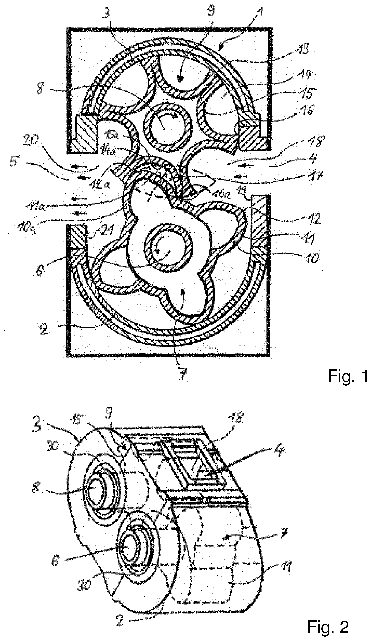
The present invention relates to a pressure reducer for a rotary internal combustion engine. The pressure reducer has a high expansion capacity with a large mechanical potential. It requires a small number of components and has a long service-life. The expansion of the pressure expansion chamber is used to reduce the pressure of gases trapped during the rotation of the rotors within the housing, ensuring a reliable pressure release. The design of the rotors enhances the expansion efficiency. The pressure reducer can be produced at low costs. The meshing toothed wheels fixed on the shafts allow for a precise coordination of the rotors. The first and second shafts comprise means for reducing a pressure exerted on the shafts during operation of the rotary internal combustion engine. The use of this pressure reducer results in an enhanced pressure expansion after the combustion step in the engine cycle, leading to a high efficiency level of the engine.

Problems solved by technology

Such arrangements often are subject to a high level of wear, which impacts the expansion capacity of the engine.

Method used


Image

  • Pressure reducer for rotary internal combustion engine

Examples


Embodiment Construction

[0006]It is an object of the invention to improve a pressure reducer for a rotary internal combustion engine, in particular to provide such a pressure reducer with a high expansion capacity and enlarged mechanical potential, which needs a small number of components, and has a long service-life.

[0007]These and other objects, which will appear from the description below, are achieved by a pressure reducer for a rotary internal combustion engines set forth in the appended independent claim. Preferred embodiments are defined in the dependent claims.

[0008]In particular the objects of this invention are realized by the following technical solutions. According to the invention a pressure reducer for a rotary internal combustion engine comprises a housing, which accommodates a first shaft and a second shaft running parallel to each other through the housing. Further the pressure reducer comprises a first rotor on the first shaft and a second rotor on the second shaft. The first rotor and th...


PUM


Abstract

A pressure reducer for a rotary internal combustion engine comprises a housing (1) accommodating a first shaft (6) and a second shaft (8) running parallel to each other through the housing (1), and a first rotor (7) on the first shaft (6) and a second rotor (9) on the second shaft (8). The first rotor (7) and the second rotor (9) are configured in a meshing arrangement, when the first shaft (6) and the second shaft (8) rotate in counter direction to each other. The first rotor (6) comprises several radial extensions (10) having convex shaped outer flanks (11), and the second rotor (9) comprises several radial wings (13) defining indentations (14) between two wings (13) having a concave shaped surface (15). A pressure expansion chamber (17) is defined by a volume between a convex shaped flank (11a) of an extension (10a) of the first rotor (7) and a concave shaped surface (15a) of an indentation (14a) of the second rotor (9), such that an outer tip (12a) of the radial extension (10a) abuts on the concave shaped surface (15a) of the indentation (14a) and an outer edge (16a) of the indentation (14a) abuts on the convex shaped flank (11a) of the extension (10a). In rotation the tip (12a) slides over the concave surface (15a) of the indentation (14a) and the edge (16a) of the indentation (14a) slides along the convex flank (11a), thereby expanding the volume of the pressure expansion chamber (17).

Description

FIELD OF INVENTION[0001]The invention relates generally to a pressure reducer (also called “expander”) for rotary internal combustion engines, and more specifically, to a pressure reducer having intermeshing rotors.BACKGROUND ART[0002]Rotary internal combustion engines take advantage of a cycle of distinct intake, compression, combustion-expansion and exhaust processes as in a four stroke cycle. Pressure reducers are used in the combustion cycle for expanding gases passing through the engine before they are exhausted.[0003]The basic example of such an engine is the Wankel engine. In a modern version a stator is in the shape of a two-lobed epitrochoid and a rotor is a trochoid. This symmetrical trochoid rotor revolves on a large bearing on the crank arm of the crankshaft which is an eccentric on the driveshaft. The three tips of the trochoid rotor have tip seals. An internal gear on the rotor, concentric with the rotor bearing, constrains the rotor to a planetary motion about a sun g...

Claims


Application Information

Patent Timeline
IPC IPC(8): F01C1/16F04C18/16
CPCF01C1/16F04C18/16F04C2240/60F04C2240/30F04C2240/20F01C1/084
Inventor MOUSSA, SAMUEL
Owner COGENERGY SUISSE SA
Learn More