
Switching controller circuit and method for controlling flyback power converter

a controller circuit and controller technology, applied in the direction of electric variable regulation, process and machine control, instruments, etc., can solve the problems of poor power conversion efficiency of the flyback power converter b>1/b>

Active Publication Date: 2021-04-29
RICHTEK TECH
View PDF0 Cites 2 Cited by
  • Summary
  • Abstract
  • Description
  • Claims
  • Application Information

AI Technical Summary

Benefits of technology

The technical effect of this patent is that it describes a method for achieving soft switching of a primary switch during the next cycle by using a negative current from the output voltage. This is achieved by turning on the secondary side winding.

Problems solved by technology

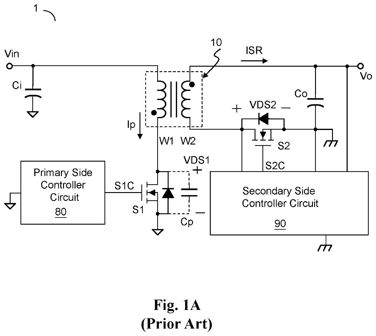
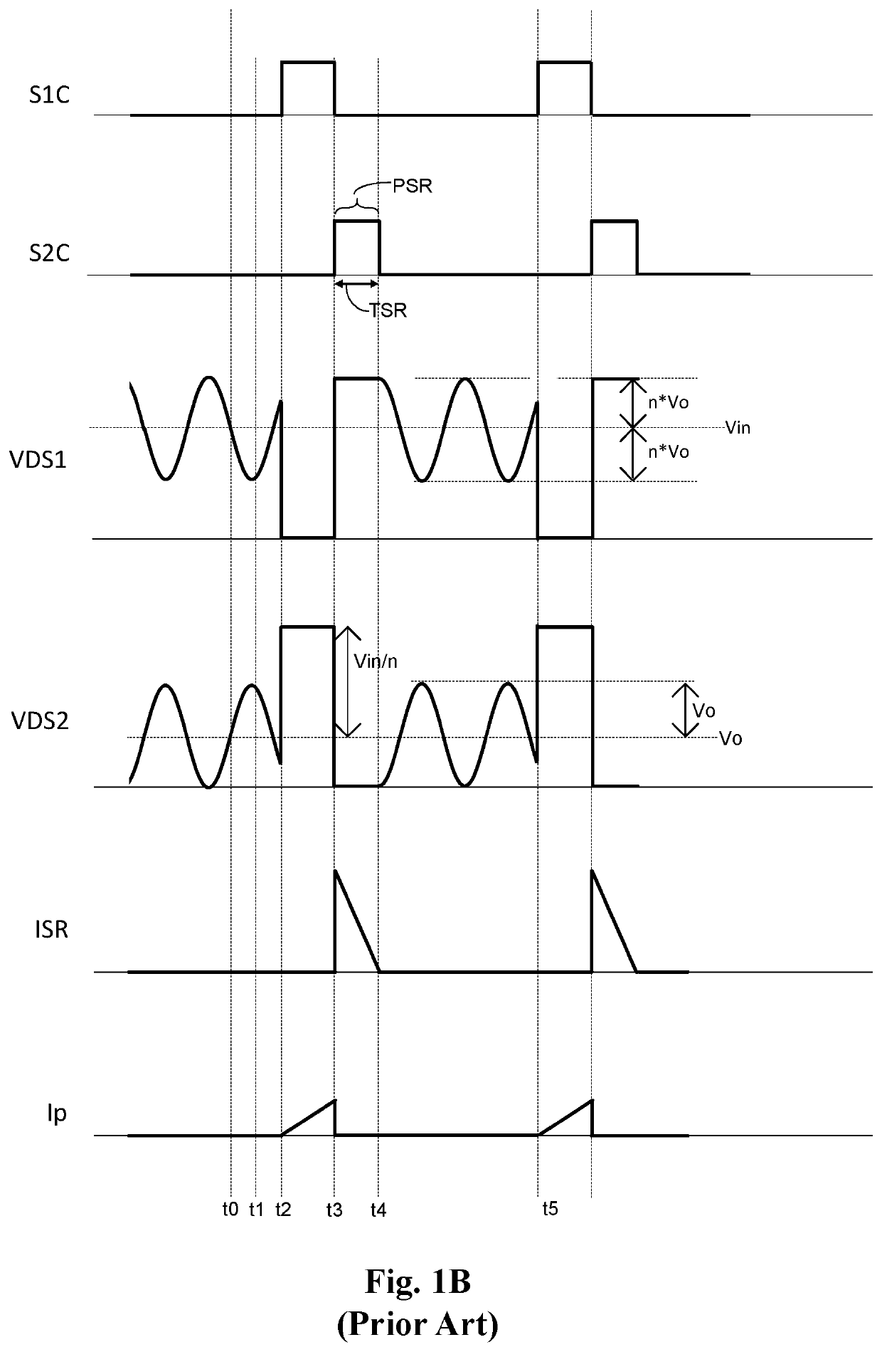
The prior art shown in FIG. 1A and FIG. 1B has the following drawbacks that: the SR switch S2 cannot be in precise synchronization with the primary side switch S1 at the primary side, and if the primary side switch S1 does not perform soft switching (SS), the flyback power converter 1 will have poor power conversion efficiency.

Method used


Image

  • Switching controller circuit and method for controlling flyback power converter
  • Switching controller circuit and method for controlling flyback power converter
  • Switching controller circuit and method for controlling flyback power converter

Examples


Embodiment Construction

[0040]The drawings as referred to throughout the description of the present invention are for illustration only, to show the interrelations between the circuits and the signal waveforms, but not drawn according to actual scale of circuit sizes and signal amplitudes and frequencies.

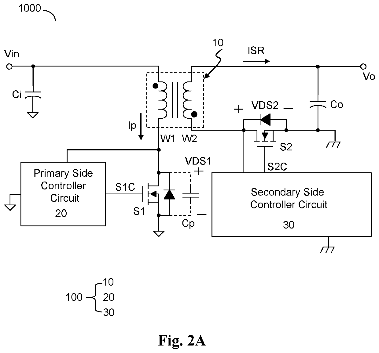
[0041]Please refer to FIG. 2A, which shows a schematic diagram of a switching controller circuit (i.e., switching controller circuit 100) according to an embodiment of the present invention. As shown in FIG. 2A, the switching controller circuit 100 is configured to operably control a flyback power converter 1000, so as to convert an input voltage Vin to an output voltage Vo. The thus generated output voltage Vo is supplied as power to a load circuit (not shown; a load circuit is well known to those skilled in the art, so the details thereof are not redundantly explained here). The switching controller circuit 100 comprises: a power transformer 10, a primary side controller circuit 20 and a secondary side c...


PUM


Abstract

A switching controller circuit for controlling a flyback power converter includes: a power transformer, a primary side controller circuit and a secondary side controller circuit. The power transformer is coupled between the input voltage and the output voltage in an isolated manner. The primary side controller circuit controls a primary side switch of the flyback power converter. The secondary side controller circuit generates a synchronous rectification (SR) signal, to control an SR switch of the flyback power converter. The SR signal includes an SR pulse and a soft switching (SS) pulse. The SR pulse controls the SR switch to be ON for an SR period, to achieve synchronous rectification at the secondary side. The SS pulse controls the SR switch to be ON for an SS period, to achieve soft switching of the primary side switch.

Description

CROSS REFERENCE[0001]The present invention claims priority to U.S. 62 / 925,724 filed on Oct. 24, 2019 and claims priority to TW 109106700 filed on Mar. 2, 2020.BACKGROUND OF THE INVENTIONField of Invention[0002]The present invention relates to a switching controller circuit; particularly, it relates to such switching controller circuit capable of controlling a flyback power converter. The present invention also relates to a method for controlling a flyback power converter.Description of Related Art[0003]The following prior arts are relevant to the present invention: K.-H. Chen, T.-J. Liang, “Design of Quasi-resonant flyback converter control IC with DCM and CCM operation”, IEEE International Power Electronics Conference, 2014; U.S. Pat. No. 8,917,068 B2, S. Chen, J. Jin, “Quasi-resonant controlling and driving circuit and method for a flyback converter”, 2014; US 2011 / 0305048 A1, T.-Y. Yang, Y.-C. Su, C.-C. Lin, “Active-Clamp Circuit for Quasi-Resonant Flyback Power Converter”, 2011;...

Claims


Application Information

Patent Timeline
Patent Type & Authority Applications(United States)
IPC IPC(8): H02M3/335H02M1/08
CPCH02M3/33592H02M2001/0058H02M1/08H02M3/33523Y02B70/10H02M1/0058
Inventor CHANG, WEI-HSUYANG, TA-YUNGCHEN, YU-CHANGCHEN, CHAO-CHILI, CHUH-CHINGLO, LI-DICHUNG, HAO-WEN
Owner RICHTEK TECH
Learn More