Track-bound vehicle converter

a converter and vehicle technology, applied in the direction of dc-ac conversion without reversal, power to power outlet, locomotives, etc., can solve problems such as weight gain, and achieve the effect of reducing weight and cos

Active Publication Date: 2017-05-25
BOMBARDIER TRANSPORTATION GMBH
View PDF0 Cites 2 Cited by
  • Summary
  • Abstract
  • Description
  • Claims
  • Application Information

AI Technical Summary

Benefits of technology

The invention is about a new converter that can create a smooth and symmetrical voltage waveform without the need for large harmonic filters. This is achieved by using a series resonance link and a direct converter that can control the current valves to switch at zero current. This reduces the need for isolation of different parts and also reduces the number of semiconductor devices needed for the converter. The invention also includes a shunt switch that can handle consecutive current pulses of the same polarity and can prepare the resonance link for creating a current pulse of the required polarity. Overall, the invention results in a lighter, more cost-effective converter for use in track-bound vehicles.

Problems solved by technology

This means that a multilevel voltage being nearly totally sinusoidal may be created directly on said converter output without any need of large harmonic filters resulting in a weight gain.

Method used


Image

  • Track-bound vehicle converter
  • Track-bound vehicle converter
  • Track-bound vehicle converter

Examples


first embodiment

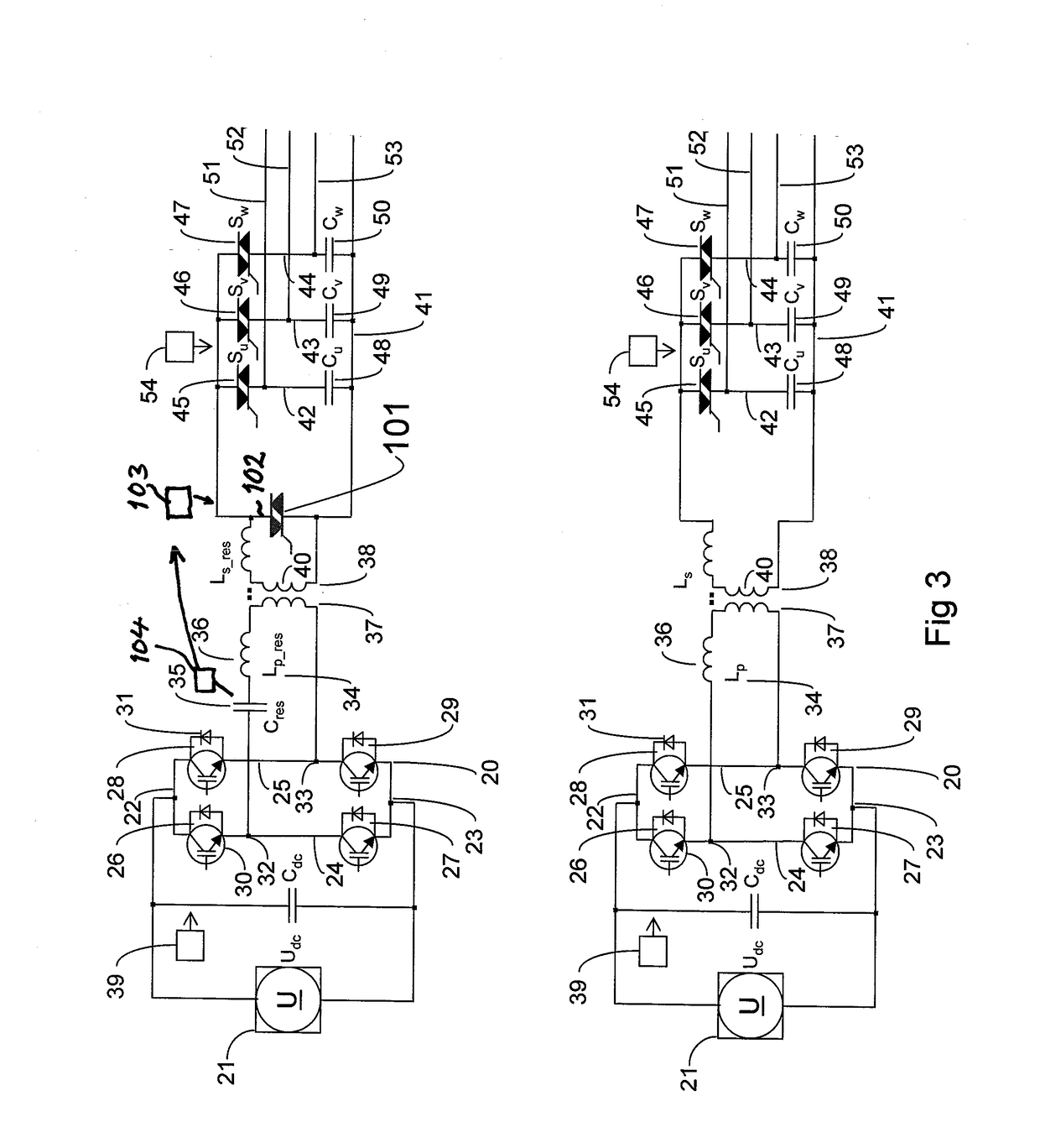
[0042]A track-bound vehicle converter according to the invention for delivering a three-phase alternating voltage on the output thereof is illustrated in FIG. 3. The values of the different parameters thereof will hereinafter by way of example be disclosed for an auxiliary converter, although a converter according to this embodiment may just as well be used as a motor converter. The converter has a block wave generator 20 configured to be connected to a direct voltage source 21, which in this example provides a direct voltage of 750 V across the terminals 22, 23 of the block wave generator. The block wave generator has two branches 24, 25 configured to be in parallel to the direct voltage source and each having two current valves 26-29 connected in series. Each current valve has a semiconductor device of turn-off type 30, here an IGBT, and a rectifying member 31, here a diode, connected in anti-parallel therewith. The two midpoints 32, 33 between the current valves of each branch fo...

second embodiment

[0050]FIG. 4 illustrates an converter according to the invention differing from the converter shown in FIG. 3 by having the series resonance link 34, or by having the inductive link when such is used, connected directly to the phase legs of the direct converter 41 with one midpoint 33 of the block wave generator branches connected to the opposite terminal of the phase legs 42-44. The converter according to this embodiment will operate in the same way as the converter shown in FIG. 3 but lack galvanic isolation between the direct voltage side and the alternating voltage side thereof. This converter is particularly suited as motor converter, whereas the one according to FIG. 3 would mostly be preferred as auxiliary converter option.

third embodiment

[0051]FIG. 5 illustrates an converter according to the invention configured to provide a single phase alternating voltage on the output thereof and differing from the converter shown in FIG. 3 by having a direct converter with only one phase leg 44′ with one switch 47′ and one second capacitor 50′.


PUM


Abstract

A track-bound vehicle converter comprises a block-wave generator (20) configured to be connected to a direct voltage source (21) and connected to a series resonance link (34), or to an inductive link, for providing the input of a direct converter (41) with semi sinusoidal current pulses. The direct converter has at least one phase leg (42-44) having on one hand one switch (45-47) connected to the link (34) and able to block voltages in both directions thereacross and conduct current in both directions therethrough and on the other a capacitor (48-50) connected in series therewith. The voltage across the capacitor (48-50) of the direct converter is used to provide a converter output with an alternating voltage.

Description

TECHNICAL FIELD OF THE INVENTION AND BACKGROUND ART[0001]The present invention relates to a track-bound vehicle converter as well as a track-bound vehicle having at least one such converter.[0002]Such a converter is arranged in a track-bound vehicle, such as a rail vehicle, for converting a direct voltage to an alternating voltage or vice versa for different purposes. The invention also includes indirect AC / AC converters, i.e. converters with two stages, interconnected on their DC sides. The invention is not restricted to any number of phases of this alternating voltage, although single phase and three phase voltages are most common, neither is the invention restricted to any particular levels of such voltages or electric power to be fed through said converter.[0003]The present invention is primarily directed to an auxiliary converter, i.e. a converter configured to deliver a voltage on the converter output to be used for electrical appliances, such as through socket outlets arrange...

Claims


Application Information

Patent Timeline
Patent Type & Authority Applications(United States)
IPC IPC(8): B60L9/28H02M7/5387H02M7/48B60L7/16B61C3/00
CPCB60L9/28B60L7/16B61C3/00H02M7/4826B60L2210/40B60L1/006B60L2200/26B60L2210/30H02M7/5387H02M7/4807B60R16/02
Inventor BANGTSSON, HANSKRUSE, LENNARTWANG, LUYU
Owner BOMBARDIER TRANSPORTATION GMBH
Why Eureka
Try Eureka