Housing for an Electric Machine with a Cooling Device

a cooling device and electric machine technology, applied in the direction of cooling/ventilation arrangement, electrical apparatus construction details, association with control/drive circuits, etc., can solve the problems of power loss and heat dissipation, and achieve space-saving arrangement and reduce the number of components

Active Publication Date: 2021-05-06
MELECS EWS GMBH & CO KG
View PDF11 Cites 1 Cited by
  • Summary
  • Abstract
  • Description
  • Claims
  • Application Information

AI Technical Summary

Benefits of technology

[0013]It is favorable for the support plate to be mounted on the heat-conducting ring. This measure makes it possible to dispense with separate structure for mounting the support plate in the housing. The heat-conducting ring, on the one hand, brings about heat dissipation from the housing and, on the other hand, functions as a bearing seat for the support plate. This results in a space-saving arrangement with regard to the st...

Problems solved by technology

Cylindrical press-on domes mechanically and thermally contact elements producing power loss.
Heat that a...

Method used


Image

  • Housing for an Electric Machine with a Cooling Device
  • Housing for an Electric Machine with a Cooling Device

Examples


Embodiment Construction

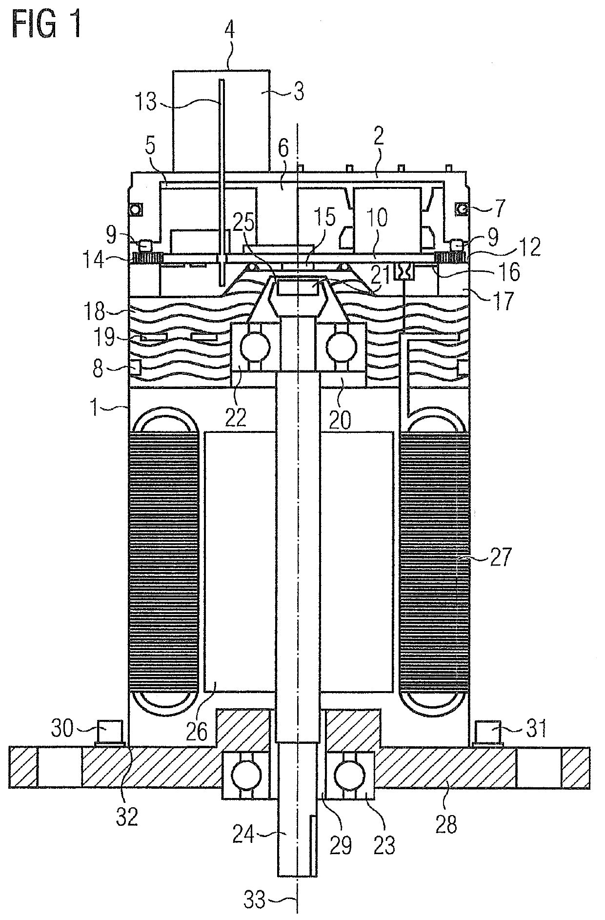
[0023]FIG. 1 is a sectional representation of an exemplary embodiment of a housing in accordance with the invention and an electric machine.

[0024]The housing has a cylindrical configuration and comprises a housing jacket 1 and a housing lid 2 inserted form-lockingly into the housing jacket 1. The housing lid 2 has a plug member 3 with an oval base and a housing opening 4. In accordance with the invention, base areas other than oval shapes are conceivable for the plug member 3.

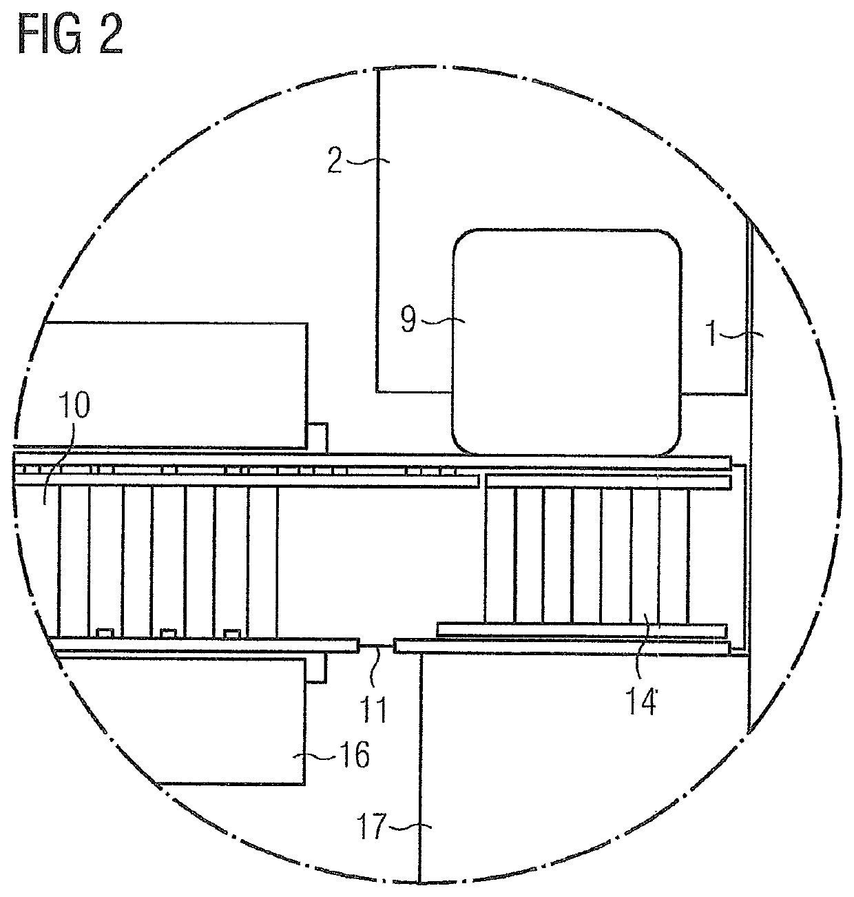
[0025]A first sealing ring 7 is arranged between the housing lid 2 and the housing jacket 1. A plug connector 13 is introduced into the housing via the housing opening 4 and connected with a cylindrical support plate 10. The circumferential surface of the support plate 10 adjoins an inner circumferential surface of the housing jacket 1 and is supplied with energy via the plug connector 13.

[0026]Two electrically insulating and vibration-damping elastic elements are provided, which are connected force-lockingly w...


PUM


Abstract

A housing for an electric machine includes a cooling device arranged on the periphery of a support plate, the cooling device contacts a heat-conducting ring connected to the housing, and the support plate as well as components arranged thereon have vibration damping and an electric insulation to provide advantageous structural conditions such that an advantageous cooling effect is achieved, and regions within the cooling device can be provided for fitting elements of the support plate.

Description

CROSS-REFERENCE TO RELATED APPLICATIONS[0001]This is a U.S. national stage of application No. PCT / EP2017 / 081779 filed Dec. 7, 2017. Priority is claimed on AT Application No. 51160 / 2016 filed Dec. 20, 2016, the content of which is incorporated herein by reference in its entirety.BACKGROUND OF THE INVENTION1. Field of the Invention[0002]The invention relates to a housing for an electric machine with a cooling device.2. Description of the Related Art[0003]The need often arises, in particular in vehicle electronics, to integrate devices with control electronics into an engine, into a transmission or into a pump etc., in order to make the best possible use of limited installation compartments and to keep conduction paths short. Heat output by support plates populated, for example, with transistors needs to be dissipated as effectively as possible via cooling devices.[0004]EP 2 429 273 A2 is known from the prior art and describes a cooling device for an electric device. An electronic circ...

Claims


Application Information

Patent Timeline
IPC IPC(8): H02K9/22H02K5/173H02K5/24H02K11/215
CPCH02K9/22H02K11/215H02K5/24H02K5/1732H02K11/33H05K1/0204H05K1/0207H05K7/20436H02K9/223H02K2211/03H02K11/30
Inventor HELLINGER, LEOPOLDNEUMANN, GERHARDLEX, MANFRED
Owner MELECS EWS GMBH & CO KG
Why Eureka
Try Eureka