Sterlizing device

Pending Publication Date: 2021-05-20
STRIX LTD
View PDF1 Cites 2 Cited by
  • Summary
  • Abstract
  • Description
  • Claims
  • Application Information

AI Technical Summary

Benefits of technology

[0037]The heated base may take any suitable form which is capable of heating the water, in use, within the chamber. For example, the heated base may be in the form of a flat plate at the base of the chamber. However, in a preferred set of embodiments, the heated base comprises a well at its center for containing water. The well effectively forms a lowered portion in the heated base in which the water resides. The Applicant has recognized that the provision of an appropriately sized well and by filling the apparatus with enough water such that only the well, or just over the well, is filled with water, all of the water within the chamber is immediately heated when the sterilization mode is initiated, and thus the production of steam is rapid. This is contrasted to filling the apparatus with a large amount of water such that the well is filled along with a sufficient portion of the chamber, as the portion of water within the chamber, rather than the water in the well, will not be in direct contact with the heated base and will thus take longer to produce steam.
[0038]The rate of production of steam, and thus the time in which the apparatus operates in the sterilization mode, will also be at least partially dictated by the how easily the steam can escape the chamber and the pressure within the chamber. In a set of embodiments the apparatus further comprises a cover arranged to close the chamber. The provision of a cover will help to at least restrict the escape of steam from the chamber and thus increase the pressure within the chamber. This cover w

Problems solved by technology

However, in various embodiments there is a temporal delay between the end of the sterilization mode and initiation of the drying mode.
However it is envisaged that the water level may be reduced to a point at which there may still be water p

Method used


Image

  • Sterlizing device
  • Sterlizing device
  • Sterlizing device

Examples


Example

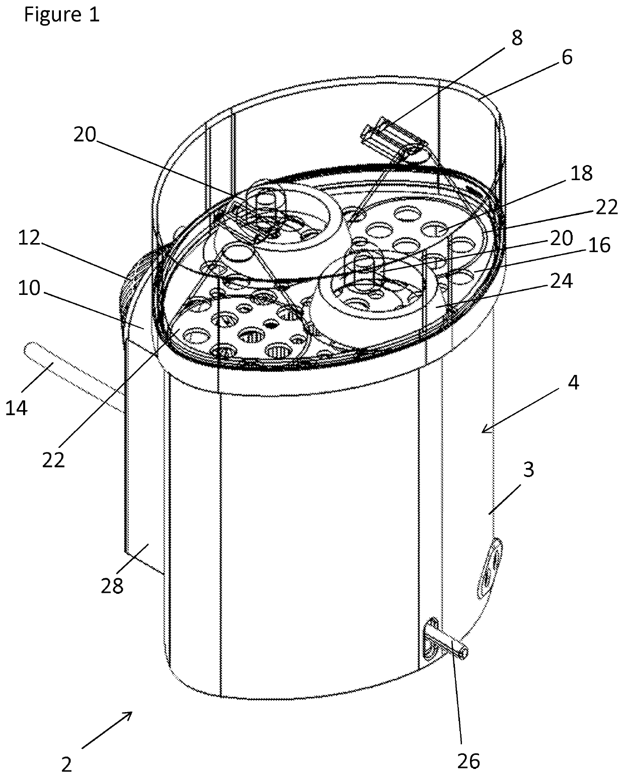
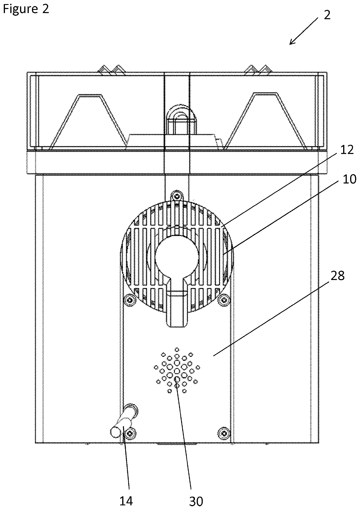
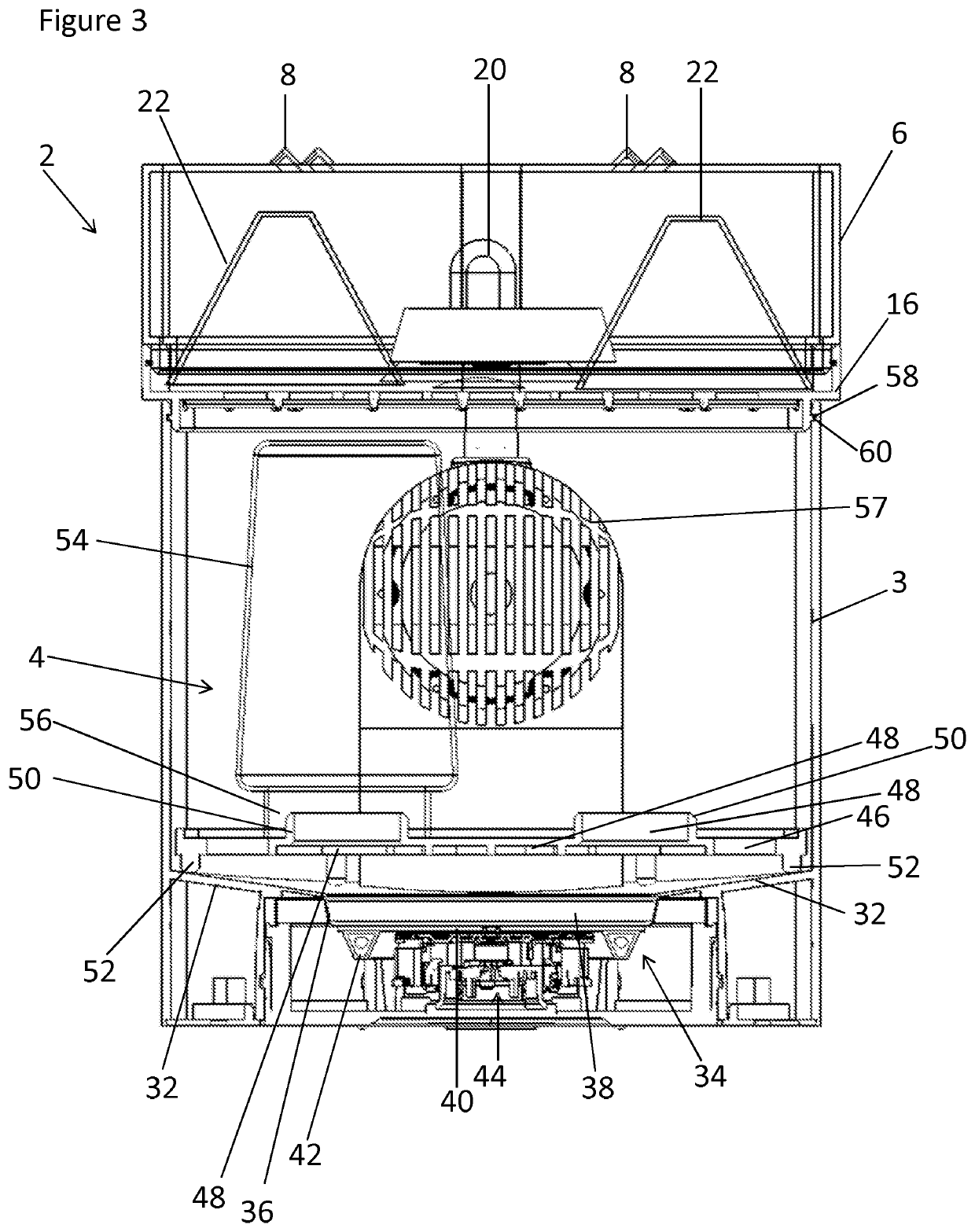
[0059]There is seen in FIG. 1 an apparatus 2 for sterilizing objects, specifically baby bottles and their associated parts. The apparatus 2 comprises an outer wall 3 which defines a main chamber 4 which is closed at its top by a cover 6. The cover 6 may be transparent or translucent to allow a user to see the objects contained within the apparatus 2. The cover 6 comprises a series of vents 8 arranged to allow steam produced within the apparatus 2 to vent. Arranged at the rear of the apparatus 2 is a forced air flow generating device in the form of an A.C. electric fan 10. The fan 10 is protected by an air intake guard 12; this component will be described in more detail later with reference to further Figures. The apparatus 2 comprises a power cord 14 which may be connected to any suitable power supply to provide power to the apparatus 2.

[0060]The apparatus 2 further comprises an upper shelf 16 arranged at the top of the chamber 4. The upper shelf 16 comprises a plurality of aperture...


PUM


Abstract

An apparatus for sterilizing objects includes a chamber with a heated base in thermal communication with an electric heating element ; a forced air flow device arranged to direct air into the chamber; an electrical power supply circuit; a thermomechanical control in series with the electric heating element and arranged to detect a temperature of the heated base; and a thermally sensitive switch in series with the forced air flow device and arranged to detect a temperature of the heated base. The apparatus is configured to operate in a sterilization mode and in a drying mode.

Description

[0001]This application is entitled to the benefit of, and incorporates by reference essential subject matter disclosed in PCT Application No. PCT / GB2018 / 053544 filed on Dec. 6, 2018, which claims priority GB Patent Appln. No. 1720442.1 filed Dec. 7, 2017, which are hereby incorporated by reference in their entireties.BACKGROUND OF THE INVENTION1. Technical Field[0002]The present invention is directed towards a sterilizing apparatus, particularly an apparatus for sterilizing baby bottles and their associated components.2. Background Information[0003]Until a baby has reached around one year old, it is regarded as necessary to sterilize all feeding equipment before each use. For example, feeding bottles, along with their associated parts including teats and covers, must be sterile before use. Sterilization prior to each use ensures that any bacteria present on the equipment is killed and therefore helps to avoid the baby becoming ill from use of the equipment.[0004]There are various wa...

Claims


Application Information

Patent Timeline
IPC IPC(8): A61L2/07A61L2/24F26B3/04F26B9/00F26B21/06
CPCA61L2/07A61L2/24F26B3/04F26B9/003A61L2202/23A61L2202/122A61L2202/14A61L2202/11A61L2202/15F26B21/06
Inventor MOUGHTON, COLIN PETER
Owner STRIX LTD
Why Eureka
Try Eureka