Planning and/or control system for a neuromodulation system

a neuromodulation and control system technology, applied in the field of tissue stimulating system control systems, can solve the problems of limited freedom of neuromodulation, motor deficit, sensory deficit, in autonomic dysfunction, etc., and achieve the effect of reducing the intensity of stimulation

Pending Publication Date: 2021-05-20
ONWARD MEDICAL NV
View PDF1 Cites 0 Cited by
  • Summary
  • Abstract
  • Description
  • Claims
  • Application Information

AI Technical Summary

Benefits of technology

[0034]In some embodiments, the Euclidean distance may be the ordinary distance between two points, here two electrodes and/or points of two electrodes. In some embodiments, it may be the straight-line distance between two points and/or two electrodes and/or two points of electrodes. In some embodiments, in a stimulation zone comprising more than two electrodes, this may have the advantage that the distance and the weighting of two electrodes is not affected by the addition of a third electrode to the analysis. Overall, weighting of each electrode of a stimulation zone and/or stimulation direction, based on the absolute and/or relative distance of the respective electrode of the stimulation zone and/or stimulation direction to one point of the stimulation zone and/or stimulation direction may be enabled. This may provide decreased stimulation intensity, the further an electrode of the stimulation zone is positioned away from a specific stimulation center of a stimulation zone. This may enable close to natural stimula

Problems solved by technology

Spinal cord injury (SCI), but also other disorders (e.g. stroke, multiple sclerosis, autonomic failure, autonomic neuropathy or cancer of the neurological tissue which impair operation of descending sympathetic pathways that normally facilitate control of autonomic functions) result in motor deficits.
However, SCI also results in sensory deficits and in autonomic dysfunctions.
Currentl

Method used


Image

  • Planning and/or control system for a neuromodulation system
  • Planning and/or control system for a neuromodulation system
  • Planning and/or control system for a neuromodulation system

Examples


Embodiment Construction

[0072]Reference will now be made in detail to exemplary embodiments, discussed with regards to the accompanying drawings. In some instances, the same reference numbers will be used throughout the drawings and the following description to refer to the same or like parts. Unless otherwise defined, technical or scientific terms have the meaning commonly understood by one of ordinary skill in the art. The disclosed embodiments are described in sufficient detail to enable those skilled in the art to practice the disclosed embodiments. It is to be understood that other embodiments may be utilized and that changes may be made without departing from the scope of the disclosed embodiments. Thus, the materials, methods, and examples are illustrative only and are not intended to be necessarily limiting.

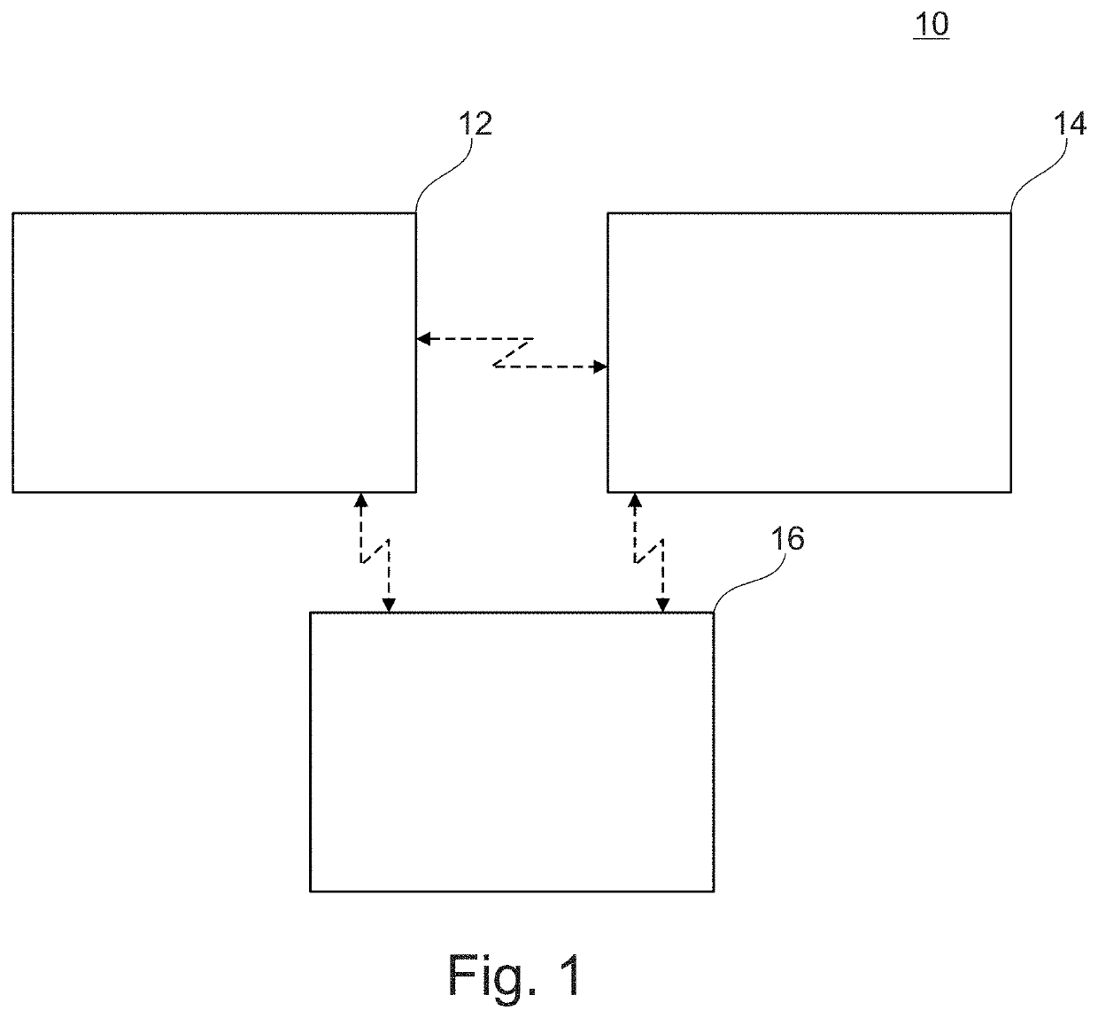
[0073]FIG. 1 shows a schematic overview of an embodiment of the planning and / or control system 10 for a system for providing neuromodulation, especially neurostimulation according to the disclos...


PUM


Abstract

A planning and/or control system for providing stimulation is disclosed. The system can include a graphical presentation module configured and arranged for providing graphical information about an electrode array comprising multiple electrodes and/or an implantation side for the electrode array comprising at least one target area, a selection module configured and arranged for determining a stimulation zone and/or a stimulation direction on the electrode array comprising at least one electrode and/or for individually selecting at least one electrode and/or for selecting at least one target area, and a calculation module configured and arranged for determining a contribution of currents provided by electrodes of the stimulation zone and/or stimulation direction on the electrode array and/or the at least one electrode selected and/or to the at least one target area selected.

Description

CROSS REFERENCE TO RELATED APPLICATION[0001]The present application claims priority to European Patent Application No. EP 19209911.7 filed on Nov. 19, 2019. The entire contents of the above-listed application is hereby incorporated by reference for all purposes.TECHNICAL FIELD[0002]Disclosed embodiments relate to control systems for tissue stimulating systems, in some embodiments a planning and / or control system for a system for providing neuromodulation, especially neurostimulation for a patient.BACKGROUND AND SUMMARY[0003]The disclosed embodiments further relate to a method for planning neuromodulation, and in some embodiments neurostimulation for a patient.[0004]The spinal cord is an integral part of the central nervous system (CNS). Spinal cord injury (SCI), but also other disorders (e.g. stroke, multiple sclerosis, autonomic failure, autonomic neuropathy or cancer of the neurological tissue which impair operation of descending sympathetic pathways that normally facilitate contr...

Claims


Application Information

Patent Timeline
IPC IPC(8): A61N1/36A61N1/05A61N1/372
CPCA61N1/36189A61N1/0551A61N1/37282A61N1/36125A61N1/36185A61N1/3606A61N1/36062A61N1/36003A61N1/36157A61N1/36182A61N1/37247G16H20/30G16H40/63A61N1/36128G06F3/0482G06F3/04847G06F3/0488
Inventor BROUNS, ROBINBAKKER, JURRIAANCABAN, MIROSLAV
Owner ONWARD MEDICAL NV
Why Eureka
Try Eureka