Mobile charging stations with fuel-cell generators for electric-drive vehicles

Active Publication Date: 2021-05-27
GM GLOBAL TECH OPERATIONS LLC
View PDF31 Cites 4 Cited by
  • Summary
  • Abstract
  • Description
  • Claims
  • Application Information

AI Technical Summary

Benefits of technology

[0002]Current production motor vehicles, such as the modern-day automobile, are originally equipped with a powertrain that operates to propel the vehicle and power the vehicle's onboard electronics. In automotive applications, for example, the vehicle powertrain is generally typified by a prime mover that delivers driving power through an automatic or manually shifted power transmission to the vehicle's final drive system (e.g., differential, axle shafts, road wheels, etc.). Automobiles have historically been powered by a reciprocating-piston type internal combustion engine (ICE) assembly due to its ready availability and relatively inexpensive cost, light weight, and overall efficiency. Such engines include compression-ignited (CI) diesel engines, spark-ignited (SI) gasoline engines, two, four, and six-stroke architectures, and rotary engines, as some non-limiting examples. Hybrid electric and full electric vehicles, on the other hand, utilize alternative power sources to propel the vehicle and, thus, minimize or eliminate reliance on a fossil-fuel based engine for tractive power.
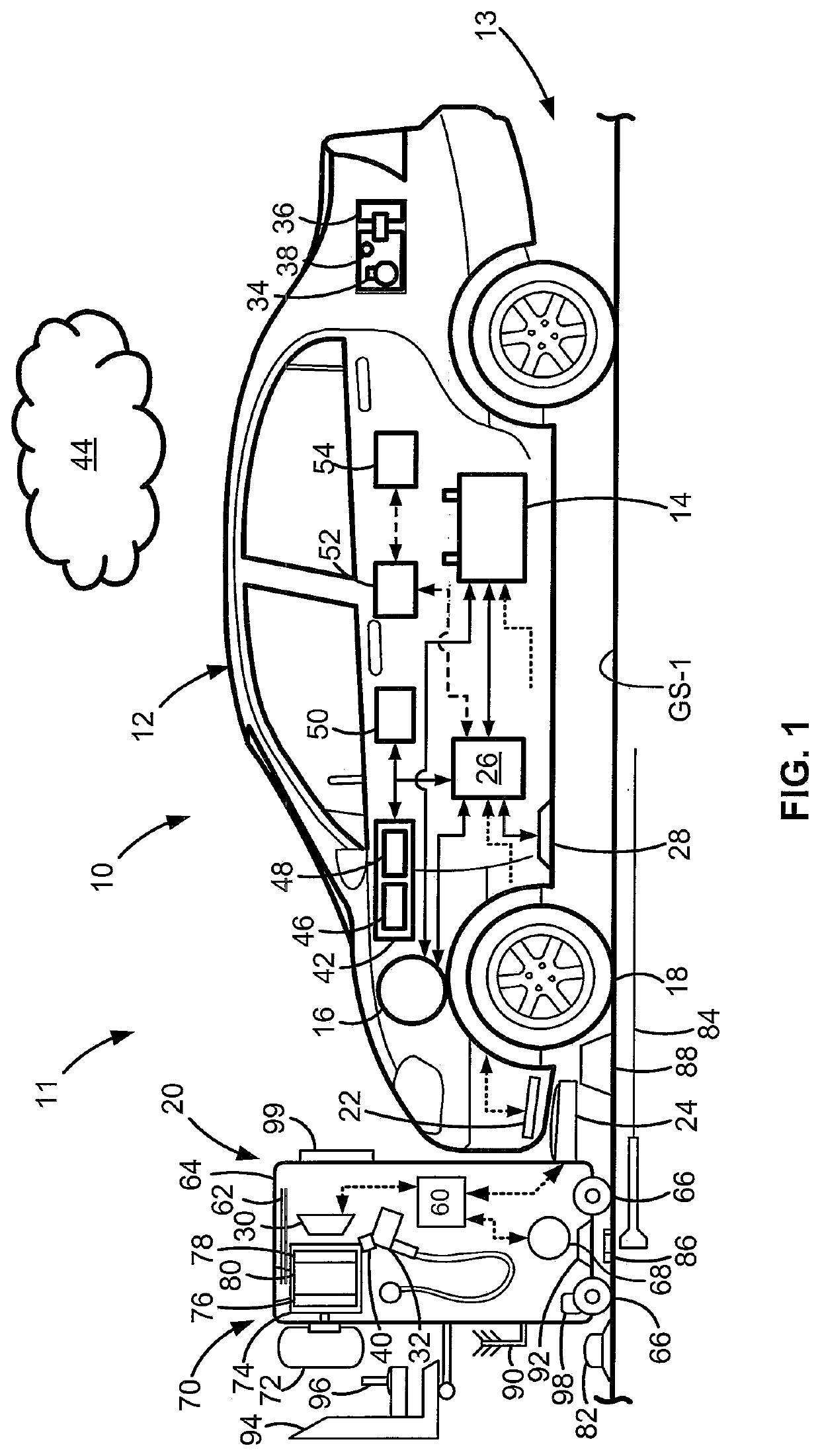
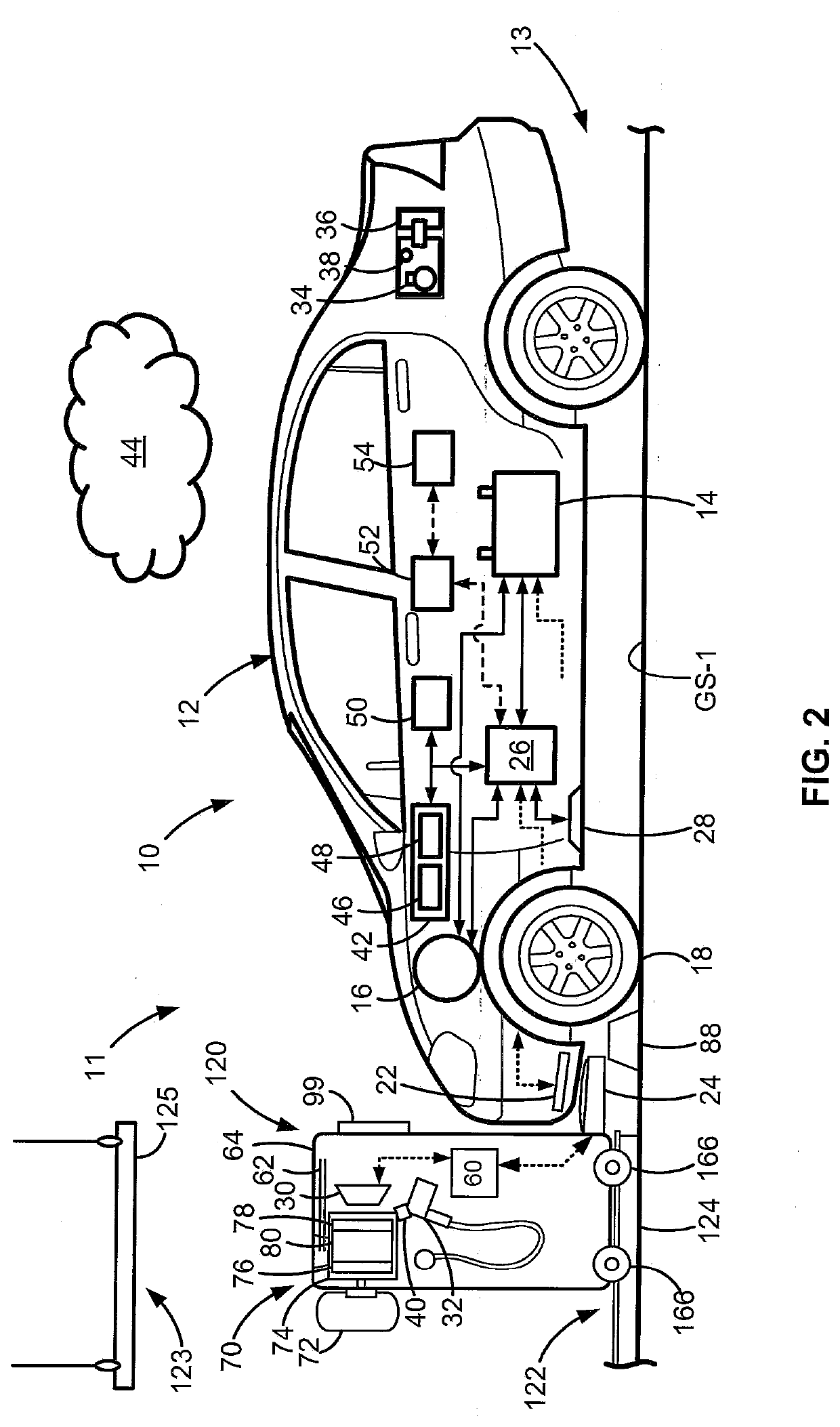
[0006]Presented herein are deployable mobile charging stations for recharging electric-drive vehicles, methods for making and methods for using such mobile charging stations, and vehicle parking facilities equipped with such mobile charging stations. By way of example, there are presented manually and self-propelled mobile charging devices to recharge batteries in vehicles parked in parking garages, parking lots, and other public or private parking facilities. Plug-in and induction direct current (DC) fast charging of electrified vehicles is enabled using a compact, high-amperage fuel cell system packaged inside a wheeled or rail-mounted EVCS. The mobile charging station uses locally stored hydrogen and, thus, eliminates the need for a combustion-based generator or wired electrical connections to utility power grids. Manual configurations may be sufficiently compact, lightweight, and mobilized to enable a single adult of average height and weight to manipulate the mobile charging station within a parking garage or lot. Autonomous implementations may automate the selective deployment of a fleet of mobile charging stations utilizing centralized and / or distributed control systems in conjunction with a network of rails, radio beacon transponders, radio-frequency (RF) emitting tracks, magnetic / colored tape, and / or via vision-guided mobility with device-embedded route planning.
[0007]Attendant benefits for many of the disclosed concepts may include eliminating the need for large-volume, grid-based EVCS that are permanently mounted to parking infrastructure. Deployable and sharable mobile charging stations eliminate the associated cost, maintenance, installation time, and dedicated space for fixed EVCS. Other attendant benefits include the use of fuel cells to enable vehicle charging, thus eliminating reliance on public electric grids that may be expensive (e.g., power factor and peak-demand penalties) or unavailable (e.g., power outages). To parking area owners, these mobile charging stations offer a relatively low financial investment as compared with installing EVCS at every spot or at every owned lot (i.e., mobile charge may can be shared amongst multiple vehicles and transported between multiple lots). To electric-drive vehicle owners, these mobile charging stations offer increased driving range with reduced range anxiety by enabling wide-spread charger distribution. To mobile charger owners / operators, these mobile charging stations offer zero hydrocarbon gas and particulate emissions, fast-charge capacity, high energy density, dynamic response to charging needs, and reduced-cost energy delivery.

Problems solved by technology

It is axiomatic that large-scale vehicle electrification in turn necessitates a concomitant buildout of readily accessible charging infrastructure that can support daily vehicle use in both urban and rural scenarios, for both short-distance and long-distance vehicle range.

Method used


Image

  • Mobile charging stations with fuel-cell generators for electric-drive vehicles
  • Mobile charging stations with fuel-cell generators for electric-drive vehicles
  • Mobile charging stations with fuel-cell generators for electric-drive vehicles

Examples


Embodiment Construction

[0018]This disclosure is susceptible of embodiment in many different forms. Representative embodiments of the disclosure are shown in the drawings and will herein be described in detail with the understanding that these embodiments are provided as an exemplification of the disclosed principles, not limitations of the broad aspects of the disclosure. To that extent, elements and limitations that are described, for example, in the Abstract, Introduction, Summary, and Detailed Description sections, but not explicitly set forth in the claims, should not be incorporated into the claims, singly or collectively, by implication, inference or otherwise.

[0019]For purposes of the present detailed description, unless specifically disclaimed: the singular includes the plural and vice versa; the words “and” and “or” shall be both conjunctive and disjunctive; the words “any” and “all” shall both mean “any and all”; and the words “including,”“containing,”“comprising,”“having,” and the like, shall e...


PUM

PropertyMeasurementUnit
peak currentaaaaaaaaaa
electrical currentaaaaaaaaaa
coloraaaaaaaaaa

Abstract

Presented are mobile charging stations for recharging electrified vehicles, methods for making / using such mobile charging stations, and parking facilities equipped with such mobile charging stations. A mobile charging station includes a frame with multiple drive wheels and a prime mover operable to drive the wheels to propel the charging station. A hydrogen storage container and fuel cell are mounted to the frame. The fuel cell oxidizes hydrogen received from the storage container to generate electrical current. An electrical coupling mechanism connects the fuel cell to a traction battery pack of an electric-drive vehicle. A resident or remote controller is programmed to receive charge requests to recharge vehicles, and responsively determines path plan data for the mobile charging station. The controller commands the prime mover to propel the mobile charging station from the charger's origin to a charger destination, and enables the fuel cell to transmit electrical current to the vehicle.

Description

INTRODUCTION[0001]The present disclosure relates generally to electrical systems for charging motor vehicles. More specifically, aspects of this disclosure relate to systems, methods, and devices for provisioning deployable charging for electric-drive vehicles.[0002]Current production motor vehicles, such as the modern-day automobile, are originally equipped with a powertrain that operates to propel the vehicle and power the vehicle's onboard electronics. In automotive applications, for example, the vehicle powertrain is generally typified by a prime mover that delivers driving power through an automatic or manually shifted power transmission to the vehicle's final drive system (e.g., differential, axle shafts, road wheels, etc.). Automobiles have historically been powered by a reciprocating-piston type internal combustion engine (ICE) assembly due to its ready availability and relatively inexpensive cost, light weight, and overall efficiency. Such engines include compression-ignite...

Claims


Application Information

Patent Timeline
Patent Type & Authority Applications(United States)
IPC IPC(8): B60L53/35H01M10/44B60L53/54B60L53/30B60L53/12B60L53/14B62D65/10B62D65/12
CPCB60L53/35H01M10/441B60L53/54B60L53/305H02J50/10B60L53/14B62D65/10B62D65/12H01M2220/20B60L53/12B60L53/38Y02T10/70Y02T10/7072Y02T90/12Y02T90/14Y02T90/16Y02E60/10B60L53/57B60L53/66H02J2300/30H02J7/0042H02J2310/48B60Y2200/92B60Y2200/91H02J7/0045G05D1/0212B60K6/22B60Y2300/91H02J7/342
Inventor MARTIN, ALAN B.KIRKLIN, MATTHEW C.FREESE, V, CHARLES E.MANN, MARGARITA M.PETTIT, WILLIAM H.
Owner GM GLOBAL TECH OPERATIONS LLC
Why Eureka
Try Eureka