
Power management system and method

a power management system and power management technology, applied in circuit monitoring/indication, transportation and packaging, and arrangement of several simultaneous batteries, etc., can solve the problems of high cost of high-specification adapters, inconvenient use, and inconvenient use of power management systems

Inactive Publication Date: 2021-06-10
FLYTECH TECH
View PDF0 Cites 0 Cited by
  • Summary
  • Abstract
  • Description
  • Claims
  • Application Information

AI Technical Summary

Benefits of technology

[0007]The present invention provides a power management system and a power management method. Firstly, a charging management unit dynamically detects electric quantities of plural battery units and a system consumption power level of a main system. Then, the charging management unit calculate

Problems solved by technology

However, the conventional power management system still has some drawbacks.
For example, since the cost of the high-specification adapter is high, the conventional power management system is not cost-effective.
Since the peripheral device with high consumption power level (e.g., the printer) is usually not operated for a long time, the surplus electric power is not fully used and wasted.
In other words, the installation cost is high.
In such way, the performance of the adapter is impaired, and the total time period of charging the plural battery units is largely increased.

Method used


Image

  • Power management system and method
  • Power management system and method
  • Power management system and method

Examples


Embodiment Construction

[0033]The present invention will now be described more specifically with reference to the following embodiments. It is to be noted that the following descriptions of preferred embodiments of this invention are presented herein for purpose of illustration and description only. In the following embodiments and drawings, the elements irrelevant to the concepts of the present invention are omitted and not shown.

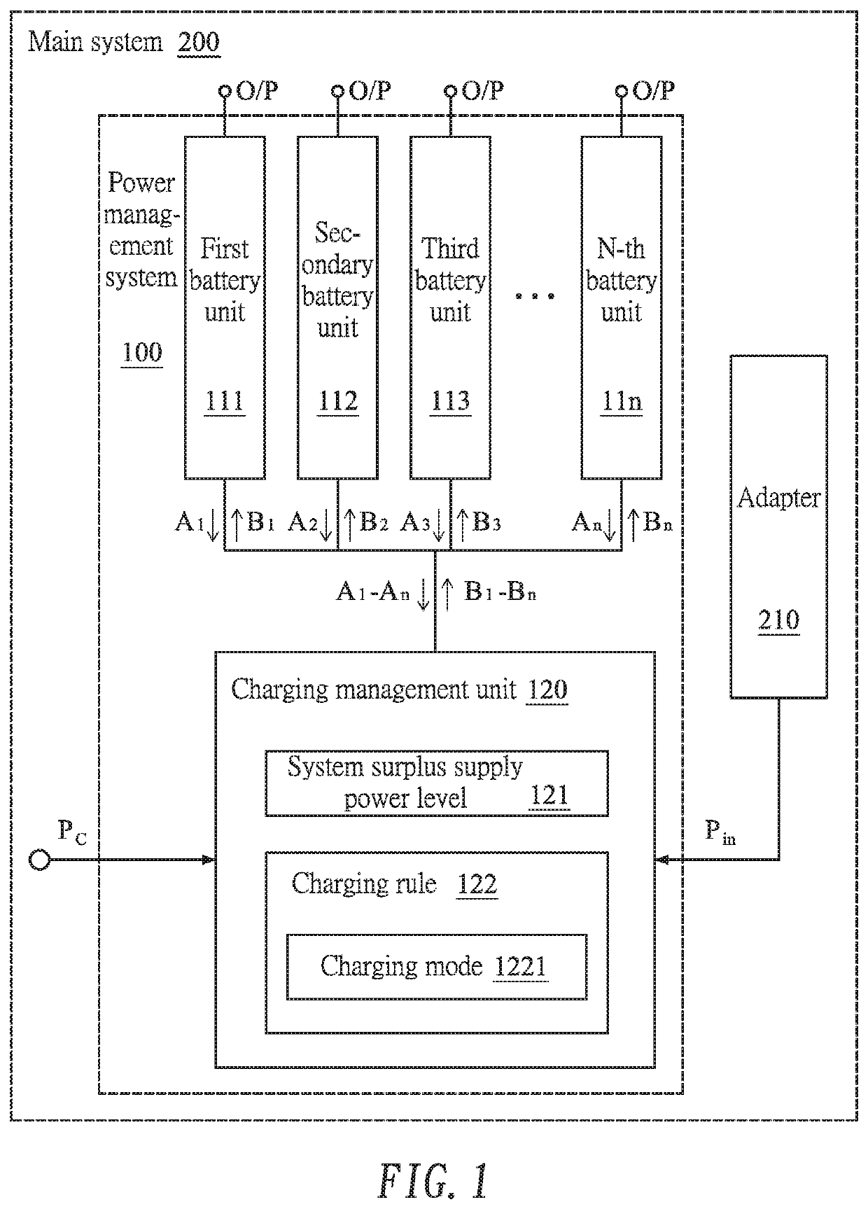
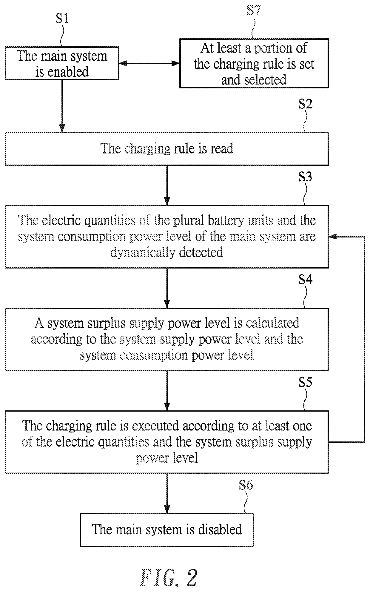
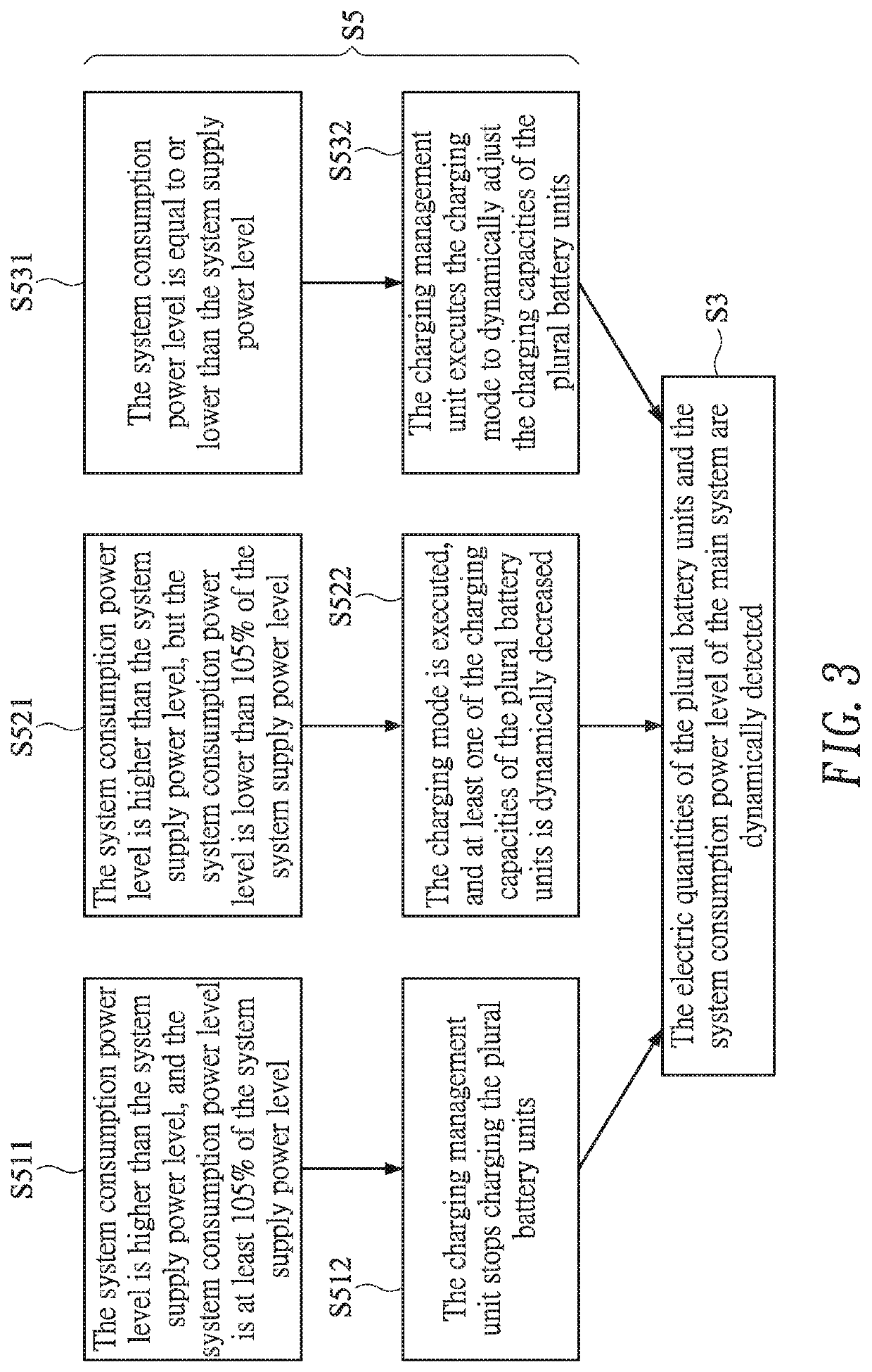
[0034]Please refer to FIGS. 1, 2, 3 and 4. FIG. 1 is a schematic functional block diagram illustrating a power management system according to an embodiment of the present invention. FIGS. 2, 3 and 4 schematically illustrate a flowchart of a power management method for the power management system as shown in FIG. 1.

[0035]As shown in FIG. 1, the power management system 100 is applied to a main system 200. The power management system 100 is electrically connected with an adapter 210 to receive a system supply power level Pin. The power management system 100 comprises plural battery ...


PUM


Abstract

A power management system and a power management method for a main system are provided. The power management system includes plural battery units and a charging management unit. A charging rule is executable by the charging management unit. The charging management unit is electrically connected with the plural battery units and the main system to dynamically detect electric quantities of the respective battery units and a system consumption power level of the main system. The charging management unit calculates a system surplus supply power level according to a system supply power level and the system consumption power level. The charging management unit dynamically adjusts charging capacities of the respective battery units according to at least one of the electric quantities, the system surplus supply power level and the charging rule.

Description

CROSS-REFERENCE TO RELATED APPLICATION[0001]This application claims priority to Taiwanese Patent Application No. 108144746, filed Dec. 6, 2019, the contents of which are incorporated herein by reference.FIELD OF THE INVENTION[0002]The present invention relates to a power management system and a power management method, and more particularly to a power management system with a charging management unit for dynamically detecting the electric quantities of plural battery units and a system consumption power level of a main system in order to dynamically adjust the priorities of charging the plural battery units and the charging capacities of the respective battery units.BACKGROUND OF THE INVENTION[0003]Generally, a main system (e.g., a POS main system) is connected with plural peripheral devices. If the number of the peripheral devices is increased and the consumption power levels of the peripheral devices are high, the main system is usually equipped with a power management system. For...

Claims


Application Information

Patent Timeline
IPC IPC(8): H02J7/00
CPCH02J7/00712H02J7/0047H02J7/0013H02J7/0014
Inventor LIU, YUN-PINGTSAI, SHUEI-JIN
Owner FLYTECH TECH
Features
  • Generate Ideas
  • Intellectual Property
  • Life Sciences
  • Materials
  • Tech Scout
  • Unparalleled Data Quality
  • Higher Quality Content
  • 60% Fewer Hallucinations
Learn More