
Atrial fibrillation detection system

Inactive Publication Date: 2021-06-17
UNION TOOL
View PDF0 Cites 0 Cited by
  • Summary
  • Abstract
  • Description
  • Claims
  • Application Information

AI Technical Summary

Benefits of technology

The present invention is an effective system for detecting atrial fibrillation by calculating the irregularity of measured pulse intervals. This system can reduce the likelihood of false positive detection, even when an extra beat occurs during measurement. The system can also provide highly reliable assessment results.

Problems solved by technology

With this condition, blood can more readily stagnate in the atrium and form a blood clot, and there is a risk that this blood clot could suddenly move to the brain and cause a stroke.
However, preparation of machinery for examining several hundred people at the same time in the manner of diagnostic tests, and analysis of ECGs measured over a long period of time, would require great cost and is not practically feasible.
However, this conventional system uses a difference between adjacent pulse intervals to detect atrial fibrillation.
Therefore, when an extrasystole other than atrial fibrillation is to be excluded, the pulse interval related to the extrasystole and the pulse intervals adjacent thereto must be excluded at the same time, and in cases where this exclusion operation is required, there is a concern that a false-positive assessment result will be detected due to the decrease in the number of pulse intervals.

Method used


Image

  • Atrial fibrillation detection system
  • Atrial fibrillation detection system
  • Atrial fibrillation detection system

Examples


example 1

[0091]A specific example 1 of the present invention is described below with reference to the diagrams.

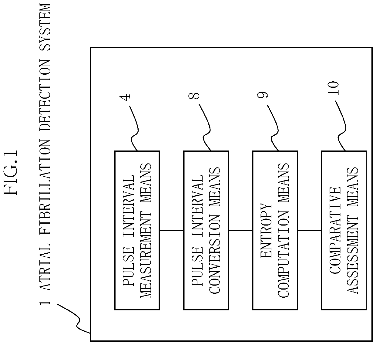
[0092]The present example is an atrial fibrillation detection system that detects whether atrial fibrillation is occurring in a subject, the atrial fibrillation detection system 1 comprising, as shown in FIG. 1: pulse interval measurement means 4 that measures the pulse intervals of a heart; pulse interval conversion means 8 that performs conversion, using a prescribed function, so that the extent of variation in the pulse intervals R obtained by the pulse interval measurement means 4 is substantially fixed; entropy computation means 9 that calculates entropy S from pulse interval images r obtained through conversion by the pulse interval conversion means 8; and comparative assessment means 10 that compares the entropy S calculated by the entropy computation means 9 and a prescribed threshold value, and that, in cases where the entropy S is greater than the threshold value, assesses...

example 2

[0126]A specific example 2 of the present invention is described below with reference to the diagrams.

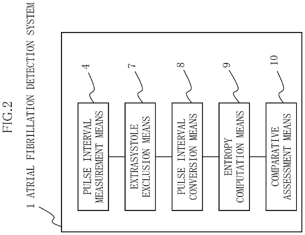
[0127]The present example shows a case where the atrial fibrillation detection system in example 1 is configured so as to furthermore comprise extrasystole exclusion means 7 that excludes pulse intervals R derived from extrasystoles other than atrial fibrillation, and to have a lower incidence of erroneous detection (false positives).

[0128]Specifically, in the atrial fibrillation detection system of Patent Document 1 (Japanese Patent No. 6150825), which is indicated as prior art, a normalized pulse interval NDR obtained through dividing the difference between adjacent pulse intervals R by the average value thereof is introduced, results in which the absolute value of the normalized pulse interval is greater than 0.1 are designated as abnormal normalized pulse intervals, and, when there are seven or more abnormal normalized pulse intervals among 20 successive normalized pulse interva...

example 3

[0149]A specific example 3 of the present invention is described below with reference to the diagrams.

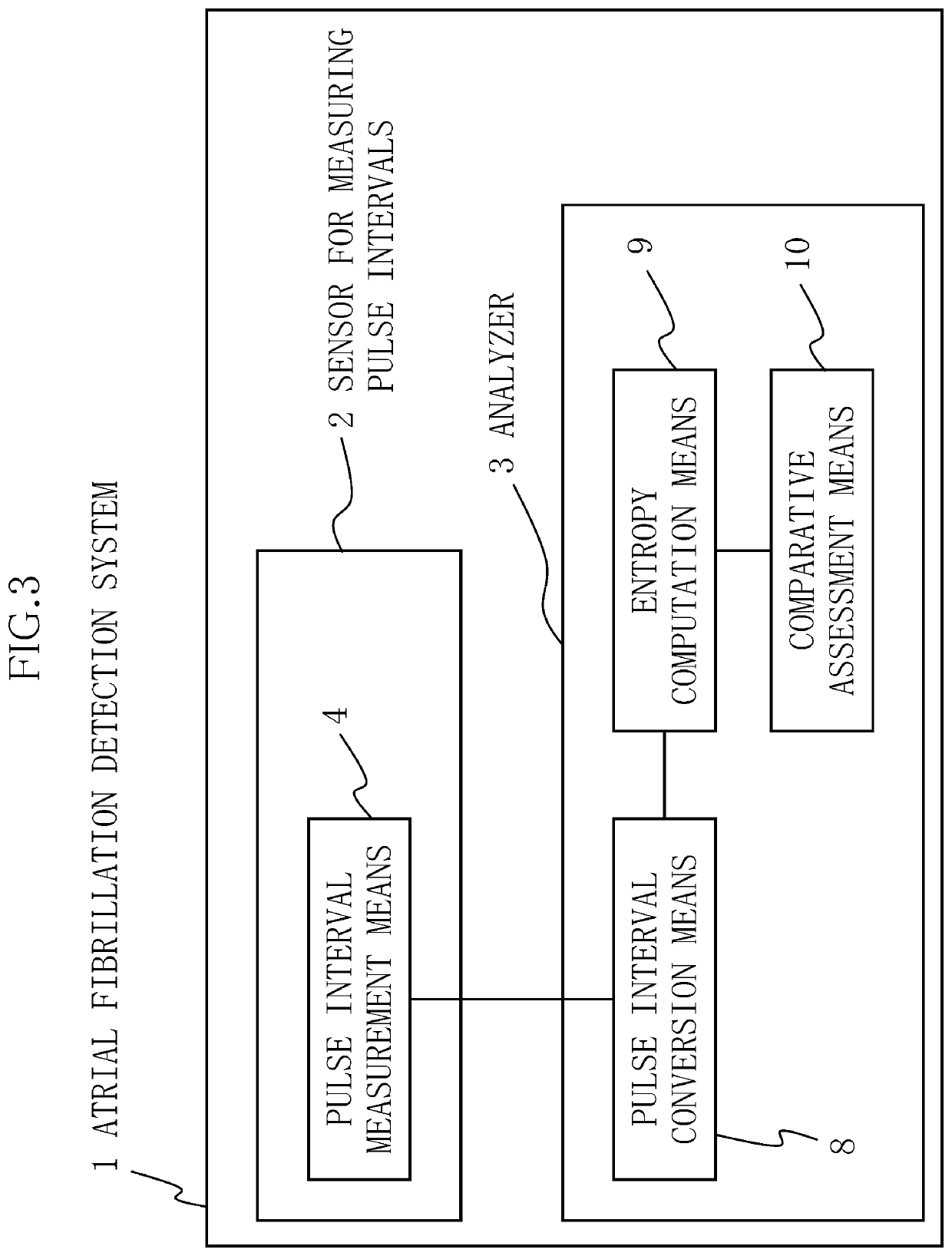
[0150]The present example has a different configuration from example 1. Whereas the atrial fibrillation detection system 1 in example 1 has a system configuration (device configuration) in which the pulse interval measurement means 4, the pulse interval conversion means 8, the entropy computation means 9, and the comparative assessment means 10 are integrated as shown in FIG. 1, the present example shows a case in which the atrial fibrillation detection system 1 has a system configuration (device configuration) comprising, as shown in FIG. 3: a small and lightweight pulse interval measurement sensor 2 for measuring pulse intervals, the pulse interval measurement means 4 being provided to the pulse interval measurement sensor 2; and an analyzer 3 in which the pulse interval conversion means 8, the entropy computation means 9, and the comparative assessment means 10 are provided.

[0151...


PUM


Abstract

An object of the present invention is to provide an atrial fibrillation detection system in which: the extent of irregularity in measured pulse intervals is calculated; even in cases where an extrasystole has occurred, detection of a false positive is reduced even when the extrasystole is not excluded; and highly reliable assessment results are obtained. An atrial fibrillation detection system comprising: pulse interval measurement means 4 that measures the pulse intervals of a heart; pulse interval conversion means 8 that performs conversion, using a prescribed function, so that the extent of variation in the pulse intervals R obtained by the pulse interval measurement means 4 is substantially fixed; entropy computation means 9 that calculates entropy S from pulse interval images r obtained through conversion by the pulse interval conversion means 8; and comparative assessment means 10 that compares the entropy S calculated by the entropy computation means 9 and a threshold value, and that, in cases where the entropy S is greater than the threshold value, assesses that atrial fibrillation is occurring.

Description

BACKGROUND OF INVENTIONTechnical Field[0001]The present invention relates to an atrial fibrillation detection system.Background Art[0002]Atrial fibrillation is a heart disease involving fine quivering of the atrium of the heart. With this condition, blood can more readily stagnate in the atrium and form a blood clot, and there is a risk that this blood clot could suddenly move to the brain and cause a stroke.[0003]According to epidemiological studies performed by the Japanese Circulation Society, the prevalence of atrial fibrillation was 0.1% for subjects in their 40s, 0.6% for those in their 50s, 0.9% for those in their 60s, and 2.7% for those in their 70s. In addition, according to the Framingham Study, the prevalence of this condition in males aged 65-84 was 3.2% in 1970, but increased over time to 9.1% in 1998.[0004]Because blood clots produced in the atrium due to atrial fibrillation reach a comparatively large size, there is said to be a strong possibility that thick blood ves...

Claims


Application Information

Patent Timeline
IPC IPC(8): A61B5/024A61B5/00G16H50/30
CPCA61B5/02405A61B5/7242A61B5/361A61B5/7225G16H50/30A61B5/7278A61B5/02433A61B5/7264A61B5/364
Inventor SHINOZAKI, RYOMATSUI, TAISHINAKATA, AKIO
Owner UNION TOOL
Learn More