

Distributor Device for a Filling Shoe for Compression Moulding
- Summary
- Abstract
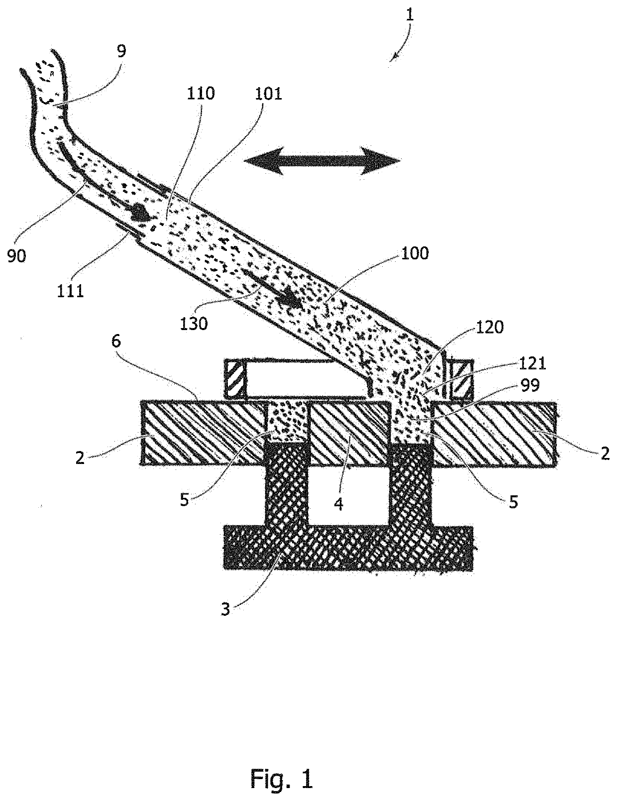
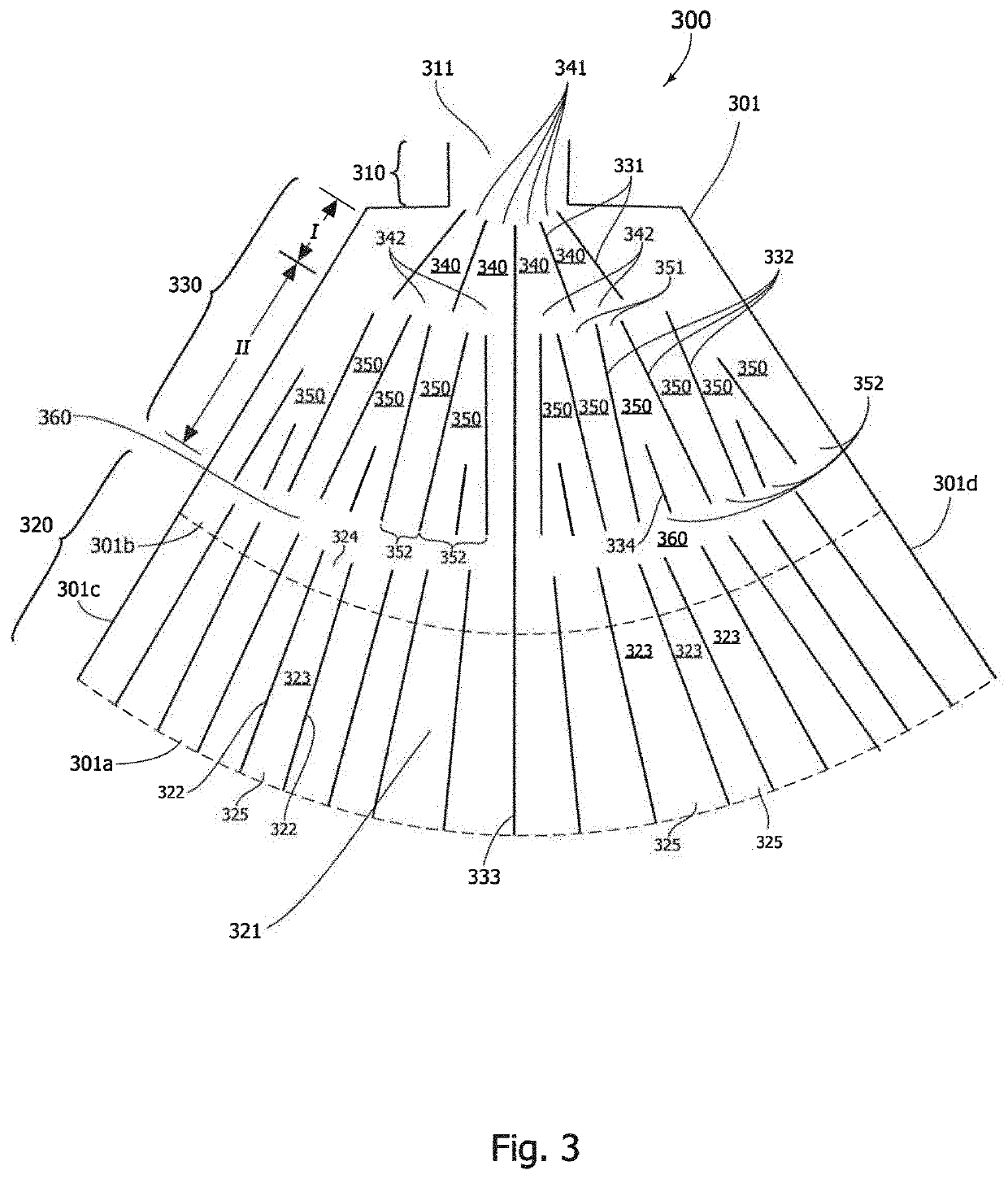
- Description
- Claims
- Application Information
AI Technical Summary
Benefits of technology
Problems solved by technology
Method used
Image

Examples
example
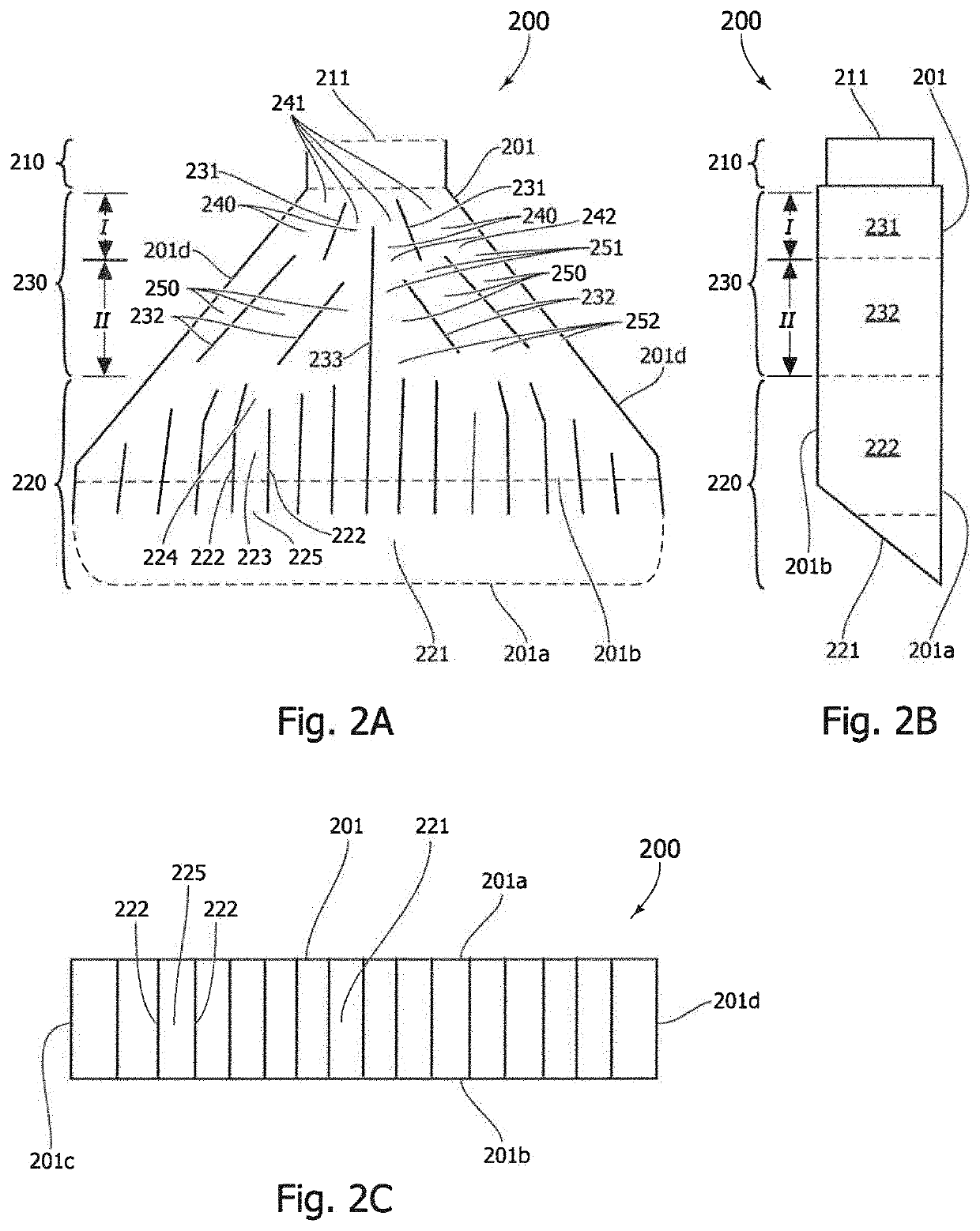
[0072]The following tables show comparative data from a production of 30 compressed green parts using identical powder material and applied compression pressure (700 Mpa) for all parts: 15 test parts were produced using a traditional filling method with 3 hoses feeding into a filling shoe forming the powder outlet for filling the mould cavity (“GAMMAL”); and further 15 test parts were produced using a filling shoe with a distributor device according to one embodiment of the invention (“NY”) The distributor device used in the filling shoe for the second set of test parts (“NY”) corresponds to the distributor device 200 according to the first embodiment shown in FIG. 2. All parts were produced from the same mould, and are therefore nominally identical. The thickness of the produced parts, a gear wheel, was then measured at four test points (‘front’, ‘back’, ‘left’, ‘right’) and the maximum difference between measured thickness values was determined for each part. A significantly reduc...
PUM
| Property | Measurement | Unit |
|---|---|---|
| Length | aaaaa | aaaaa |
| Volume | aaaaa | aaaaa |
| Ratio | aaaaa | aaaaa |
Abstract
Description
Claims
Application Information