Check patentability & draft patents in minutes with Patsnap Eureka AI!

Prosthetic Heart Valve Tether and Tether Attachment Features

a technology tethers, which is applied in the field of tethers and tether attachment features can solve the problems of a high morbidity, high cost, and high cost of prosthetic heart valves, and achieves the effects of reducing the risk of heart valve rupture, and reducing the risk of strok

Inactive Publication Date: 2021-06-17
TENDYNE HLDG
View PDF8 Cites 1 Cited by
  • Summary
  • Abstract
  • Description
  • Claims
  • Application Information

AI Technical Summary

Benefits of technology

This patent describes a prosthetic heart valve and an anchor system for securing a tether. The valve has a collapsible and expandable valve frame and a prosthetic valve assembly. The tether is a metal filament that extends through the ventricular wall when the valve is implanted. The anchor system includes an epicardial anchor and a locking mechanism. The epicardial anchor has a tether attachment member with a tether passageway. The locking mechanism is movable from a first position where it does not intersect the tether to a second position where it intersects the tether. The leading tip of the locking mechanism is designed to frictionally engage the tether without piercing it. This system ensures the tether is secure and can withstand the high pressure of blood flow through the heart.

Problems solved by technology

Prosthetic heart valves can pose particular challenges for delivery and deployment within a heart.
Valvular heart disease, specifically aortic and mitral valve disease, is a significant health issue in the United States.
While valve replacement surgery typically carries a 1-4% mortality risk in otherwise healthy persons, a significantly higher morbidity is associated with the procedure largely due to the necessity for extra-corporeal circulation.
Further, open heart surgery is often poorly tolerated in elderly patients.
This is in part reflective of the greater level of complexity associated with the native mitral valve, and thus a greater level of difficulty with regard to inserting and anchoring the replacement prosthesis.

Method used


Image

  • Prosthetic Heart Valve Tether and Tether Attachment Features
  • Prosthetic Heart Valve Tether and Tether Attachment Features
  • Prosthetic Heart Valve Tether and Tether Attachment Features

Examples


Embodiment Construction

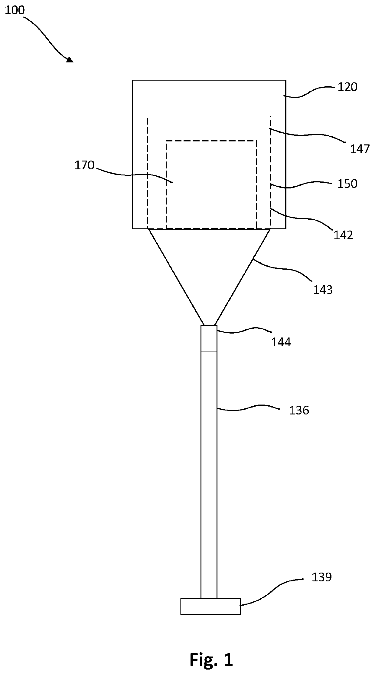
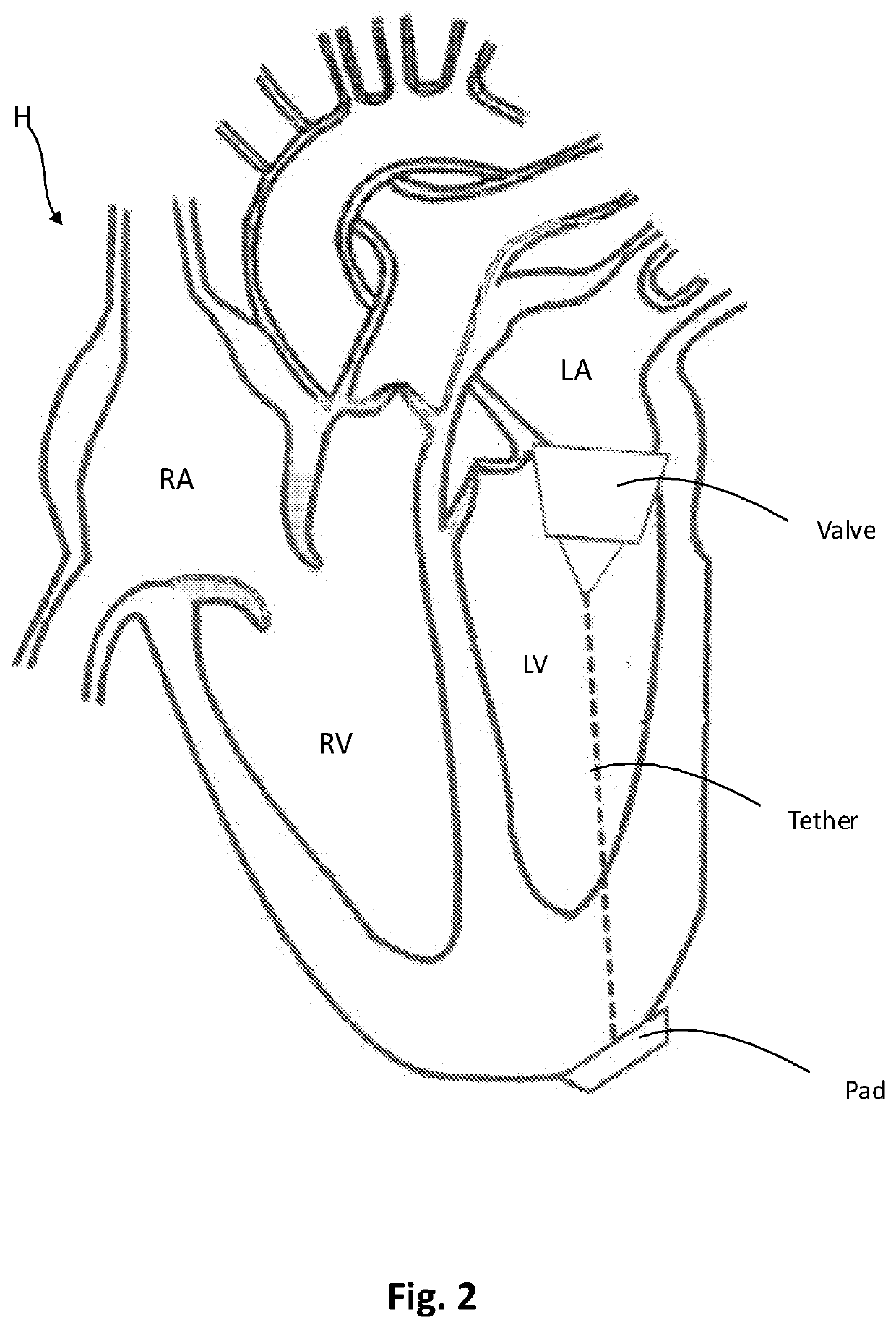
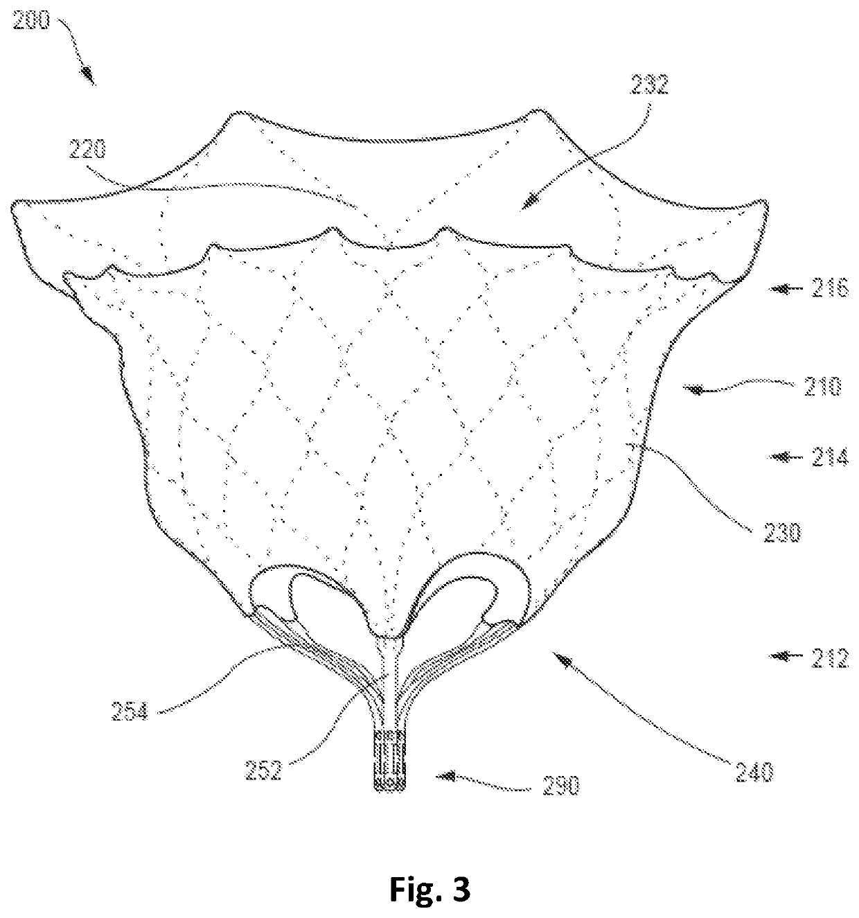
[0033]Apparatus and methods are described herein for prosthetic heart valves, such as prosthetic mitral valves or prosthetic tricuspid valves. In particular, tethers for use in securing a prosthetic heart valve within the native valve annulus are described herein, including the use of metal tethers such as tethers formed from a nickel titanium alloy such as nitinol. Additional accessory devices for use with such tethers, such as epicardial pads with features to lock the tether in a desired position, are also described herein. As used herein, the terms “substantially,”“generally,”“approximately,” and “about” are intended to mean that slight deviations from absolute, for example plus or minus 10%, are included within the scope of the term so modified. When ranges of values are described herein, those ranges are intended to include sub-ranges. For example, a recited range of 1 to 10 includes 2, 5, 7, and other single values, as well as all sub ranges within the range, such as 2 to 6, 3...


PUM


Abstract

A prosthetic heart valve may include a collapsible and expandable valve frame, and a prosthetic valve assembly disposed within the valve frame. A tether may extend between a first end and a second end, the second end being coupled to the valve frame. The tether may be formed of a metal filament and have a length sufficient to extend through a ventricular wall when the prosthetic heart valve is implanted in an atrioventricular valve annulus. An anchor system may be provided and may include an epicardial anchor and a locking mechanism to crimp or to otherwise frictionally engage the tether without piercing the tether. Additional accessory tools may be provided to assist in crimping or uncramping the tether from the epicardial pad.

Description

CROSS-REFERENCE TO RELATED APPLICATIONS[0001]This application claims the benefit of the filing date of U.S. Provisional Patent Application No. 62 / 948,871, filed Dec. 17, 2019, the disclosure of which is hereby incorporated by reference herein.BACKGROUND OF THE DISCLOSURE[0002]Embodiments are described herein that relate to devices and methods for use in the delivery and deployment of prosthetic heart valves, and particularly to tethers and tether attachment features for prosthetic heart valves.[0003]Prosthetic heart valves can pose particular challenges for delivery and deployment within a heart. Valvular heart disease, specifically aortic and mitral valve disease, is a significant health issue in the United States. Traditional valve replacement surgery involving the orthotopic replacement of a heart valve is considered an “open heart” surgical procedure. Briefly, the procedure necessitates surgical opening of the thorax, the initiation of extra-corporeal circulation with a heart-lu...

Claims


Application Information

Patent Timeline
Patent Type & Authority Applications(United States)
IPC IPC(8): A61F2/24
CPCA61F2/2418A61F2220/0058A61F2230/0023A61F2220/0008A61F2220/0075A61F2250/0039A61F2230/0054A61F2230/005A61F2/2436
Inventor DEHOOG, HENDRIK J.
Owner TENDYNE HLDG
Features
  • R&D
  • Intellectual Property
  • Life Sciences
  • Materials
  • Tech Scout
  • Unparalleled Data Quality
  • Higher Quality Content
  • 60% Fewer Hallucinations
Learn More