
End-expiratory co2 guided tracheal intubation device

Pending Publication Date: 2021-06-17
SHANGHAI NINTH PEOPLES HOSPITAL AFFILIATED TO SHANGHAI JIAO TONG UNIV SCHOOL OF MEDICINE
View PDF5 Cites 0 Cited by
  • Summary
  • Abstract
  • Description
  • Claims
  • Application Information

AI Technical Summary

Benefits of technology

The present invention is a device that helps medical professionals quickly and accurately determine the position of an endotracheal tube by detecting the end-expiratory CO2 in the patient's breath. It uses an end-expiratory CO2 sensor connected with an end-expiratory CO2 catheter and helps medical staff to safely intubate patients. Additionally, the device has a suction tube for extracting throat effusion during the intubation process, which improves work efficiency. The device also has a retractable tube segment that can be extended beyond the end face of the intubation tube to prevent harm to the human body.

Problems solved by technology

However, in the process of intubation, pus will be secreted in the larynx and trachea, forming effusion in the larynx and trachea, causing visual impairment to the endoscope and affecting the insertion of the intubation tube.

Method used


Image

  • End-expiratory co2 guided tracheal intubation device
  • End-expiratory co2 guided tracheal intubation device
  • End-expiratory co2 guided tracheal intubation device

Examples


example 1

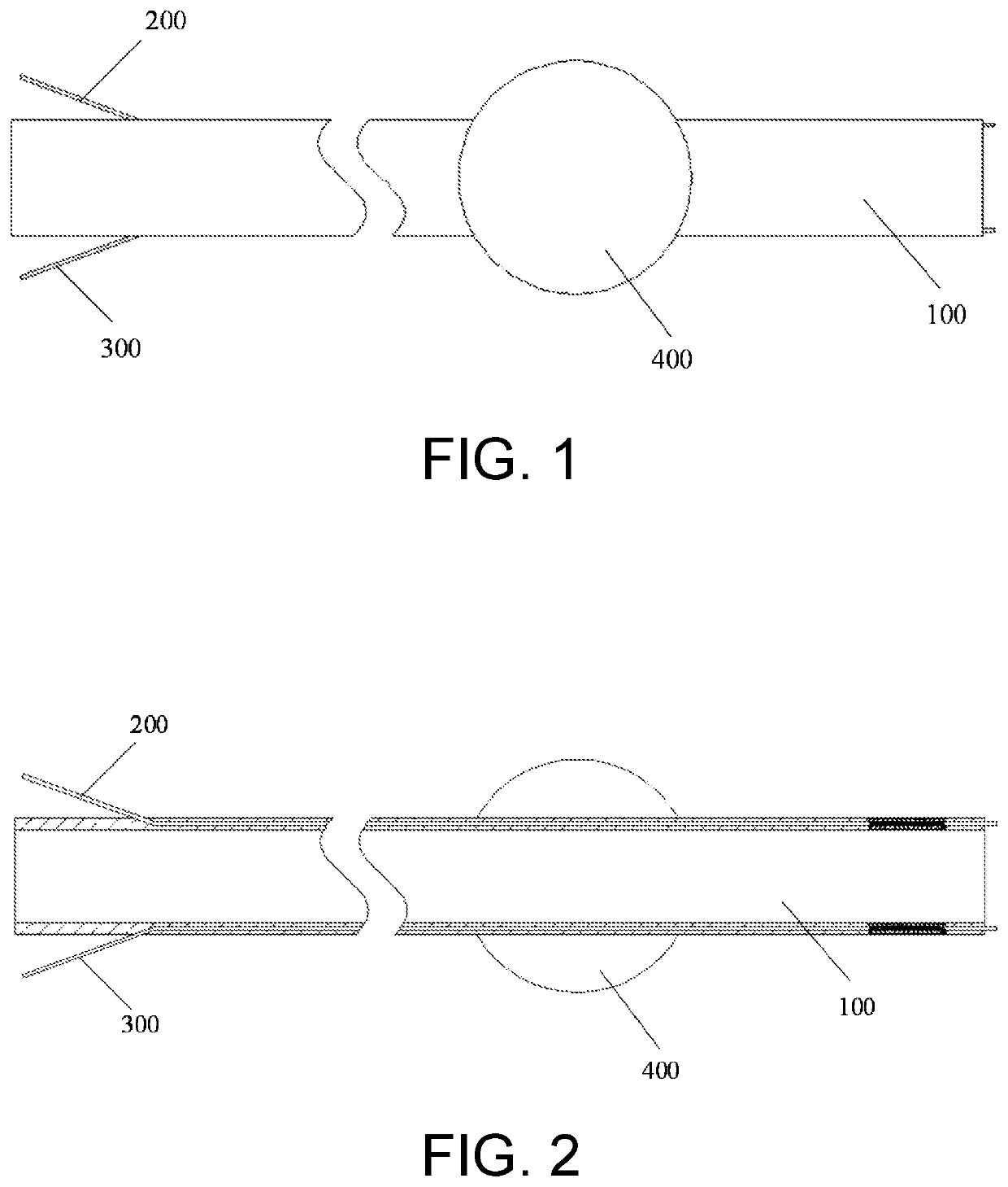
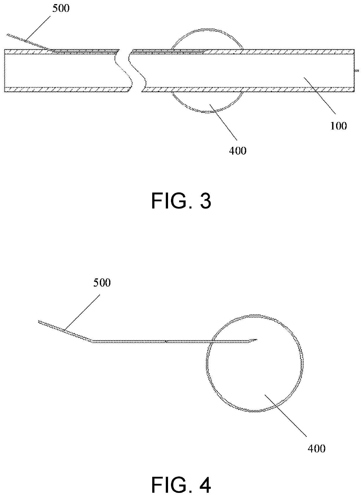
[0024]As shown in FIG. 1 and FIG. 2, an end-expiratory CO2 guided tracheal intubation device according to an embodiment of the present invention includes an intubation tube 100, an end-expiratory CO2 catheter 200, a suction tube 300, an airbag 400, and an inflatable tube 500. The end-expiratory CO2 catheter 200 partially penetrates the sidewall of the intubation tube 100, and one end thereof extends beyond the end of the intubation tube 100, and the other end is connected to the end-expiratory CO2 sensor; one end of the suction tube 300 partially penetrates the sidewall of the intubation tube 100, and the other end is connected to the air pump. In this embodiment, one end of the end-expiratory CO2 catheter 200 enters the sidewall of the intubation tube 100 from somewhere near the left end of the intubation tube 100, and extends to the right in the sidewall, and penetrates the right end face of the intubation tube 100. The other end of the CO2 catheter 200 is connected to an end-expi...

example 2

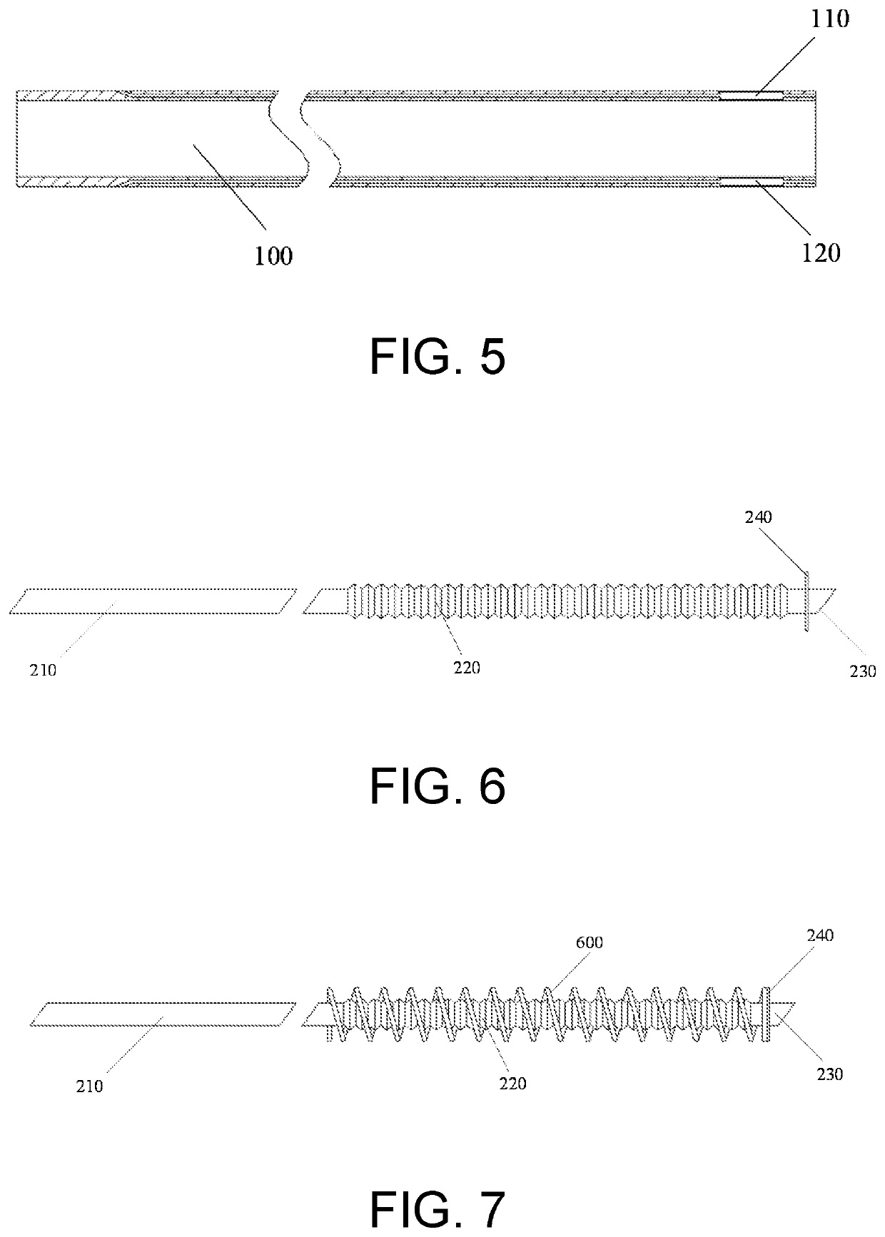
[0035]The similarities between this example and example 1 will not be described again. As shown in FIG. 5 to FIG. 7, an end-expiratory CO2 catheter installation groove 110 is provided in a sidewall of the intubation tube 100. The end-expiratory CO2 catheter 200 includes a first end tube segment 210, a first tube segment 220, and a first end tube segment 230, which are connected in sequence; the first end tube segment 210 is connected to the end-expiratory CO2 sensor; the first tube segment 220 is provided in end-expiratory CO2 catheter installation groove 110, and sleeved with a first spring 600. One end of the first spring 600 is abutted on the first stop block 240 provided on the first tail tube segment 230, and the other end thereof is abutted on an end wall of the end-expiratory CO2 catheter installation groove; the first tail tube segment 230 extends to the outside of the intubation tube 100. In this embodiment, the right end of the intubation tube 100 is inserted into the trac...


PUM


Abstract

The present invention discloses an end-expiratory CO2 guided tracheal intubation apparatus. The apparatus comprises: an intubation tube, an end-expiratory CO2 catheter, a suction tube, an airbag and an inflatable air tube, wherein the end-expiratory CO2 catheter partially penetrates the sidewall of the intubation tube, one end of the end-expiratory CO2 catheter extends beyond an end of the intubation tube, and the other end is connected to an end-expiratory CO2 sensor, the suction tube partially penetrates a sidewall of the intubation tube, one end of the liquid suction tube extends beyond an end of the intubation tube, the other end is connected to an air pump, the airbag sleeves the outer wall of the intubation tube, the inflatable air tube partially penetrates the sidewall of the intubation tube, one end thereof is connected to the airbag, and the other end is connected to the air supply device.

Description

CROSS-REFERENCE TO RELATED APPLICATION[0001]This application claims the priority benefit of China application serial no. 201911267307.7, filed on Dec. 11, 2019. The entirety of the above-mentioned patent application is hereby incorporated by reference herein and made a part of this specification.TECHNICAL FIELD[0002]The present invention relates to the technical field of medical instruments, and in particular, to an end-expiratory CO2 guided tracheal intubation device.TECHNICAL BACKGROUND[0003]Tracheal intubation refers to the placement of a special endotracheal tube into the trachea through the glottis. This technique can provide the best conditions for airway patency, ventilation and oxygen supply, aspiration of the airway, and prevention of aspiration. Emergency tracheal intubation has become an important measure in the rescue of cardiopulmonary resuscitation and critically ill patients with respiratory dysfunction. Tracheal intubation is an important rescue technique commonly us...

Claims


Application Information

Patent Timeline
IPC IPC(8): A61M16/04A61M16/00
CPCA61M16/0463A61M16/0488A61M2016/0413A61M16/0003A61M16/045A61M1/0023A61M16/0402A61M2230/40A61M2230/005A61M16/04A61M16/0434A61M16/0477A61M2210/1032A61M16/0486
Inventor JIANG, HONGXIA, MINGSUN, YUYAN, JIA
Owner SHANGHAI NINTH PEOPLES HOSPITAL AFFILIATED TO SHANGHAI JIAO TONG UNIV SCHOOL OF MEDICINE
Features
  • Generate Ideas
  • Intellectual Property
  • Life Sciences
  • Materials
  • Tech Scout
  • Unparalleled Data Quality
  • Higher Quality Content
  • 60% Fewer Hallucinations
Learn More